37 draw the shear diagram for the beam. 7.53
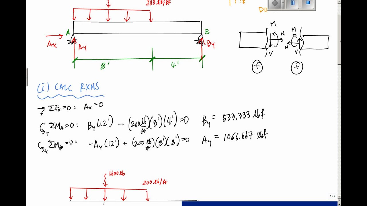
What are the reactions on the beam at A and B? Refer to Fig. 5-14(a). 1000 N OON 1 * Зш A m Ш. 372.4 N ,llmi 0 6m (a) Fig. 5-14 SOLUTION Assume the beam bends so that the wall pushes up at A and down at В on the beam. Draw the free-body diagram showing at the midpoint the gravitational force 372.4 N C.8 m X 10 kg/m X 9.8 m/s2). See Fig. 5-14F). 7-57. Draw the shear and moment diagrams for the beam.... 7-58. Draw the shear and moment diagrams for the compound beam. The beam is pin-connected at E and F.... 7-59. Draw the shear and moment diagrams for the beam.... 7-60. The beam will fail when the maximum internal moment is Mmax. Determine the position x of the concentrated force P ...
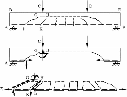
Axial Force, Shear Force and Bending Moment Diagrams for Plane Frames Previous definitions developed for shear forces and bending moments are valid for both beam and frame structures. However, application of these definitions, developed for a horizontal beam, to a frame structure will require some adjustments.

Draw the shear diagram for the beam. 7.53
The ratio of the area of the actual indicator diagram to the theoretical one is called diagram factor. Q. 5: Explain the working of any air standard cycle (by drawing it on P-V diagram) known to you. Why is it known as ‘Air standard cycle.’? (Dec–01) Or Draw the Diesel cycle on P-V coordinates and explain its functioning. Refer to the indicated problem and draw complete shear and bending moment diagrams. Show ordinates at key points and indicate magnitude of shear and moment. Neglect the beam weight Calculate the shear and bending moment at 5 m and 10 m from the left... Draw the shear and moment diagrams for the beam : 2017321 7-48. Draw the shear and moment diagrams for the beam (a) in terms of the parameters shown; (b) set M 0 = 500 N · m, L = 8 m.
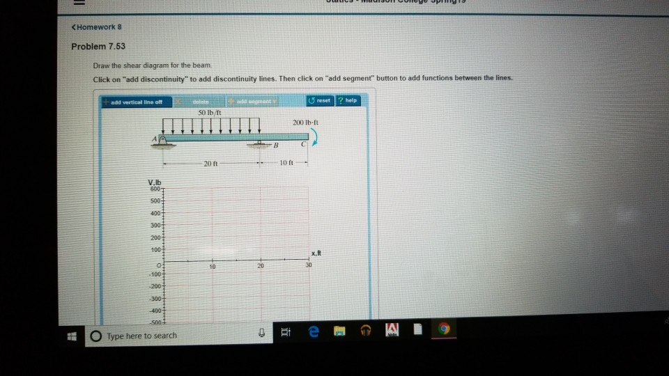
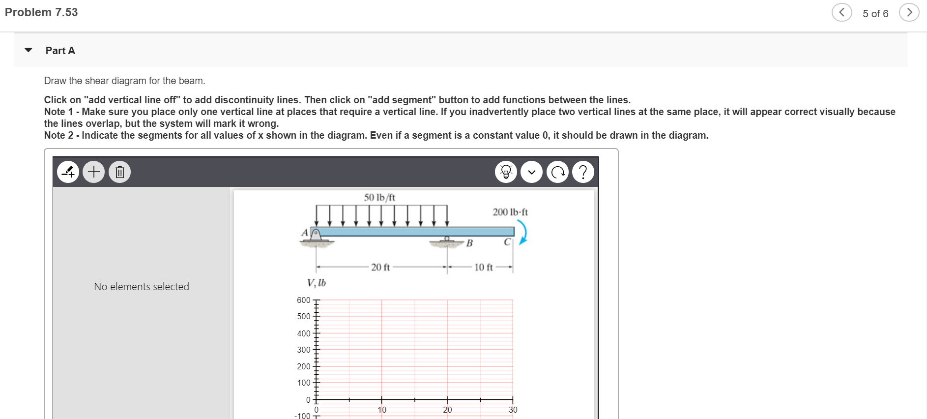
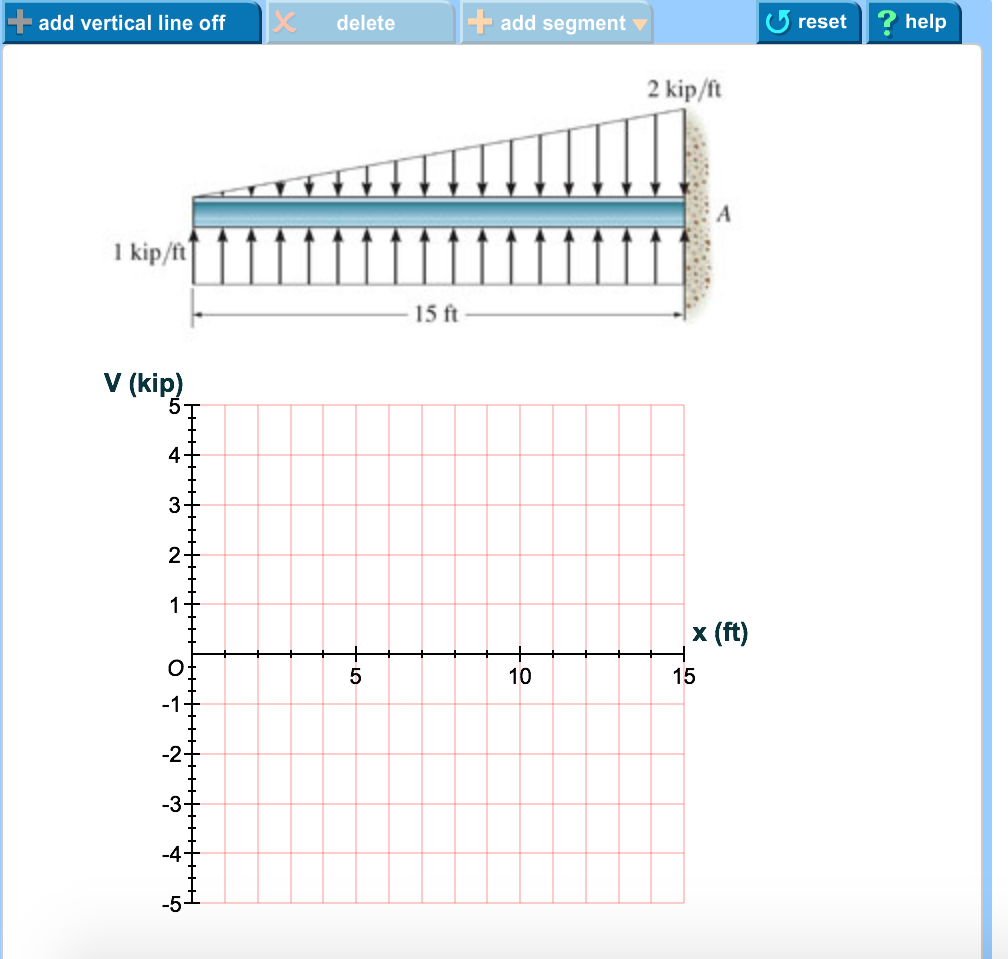
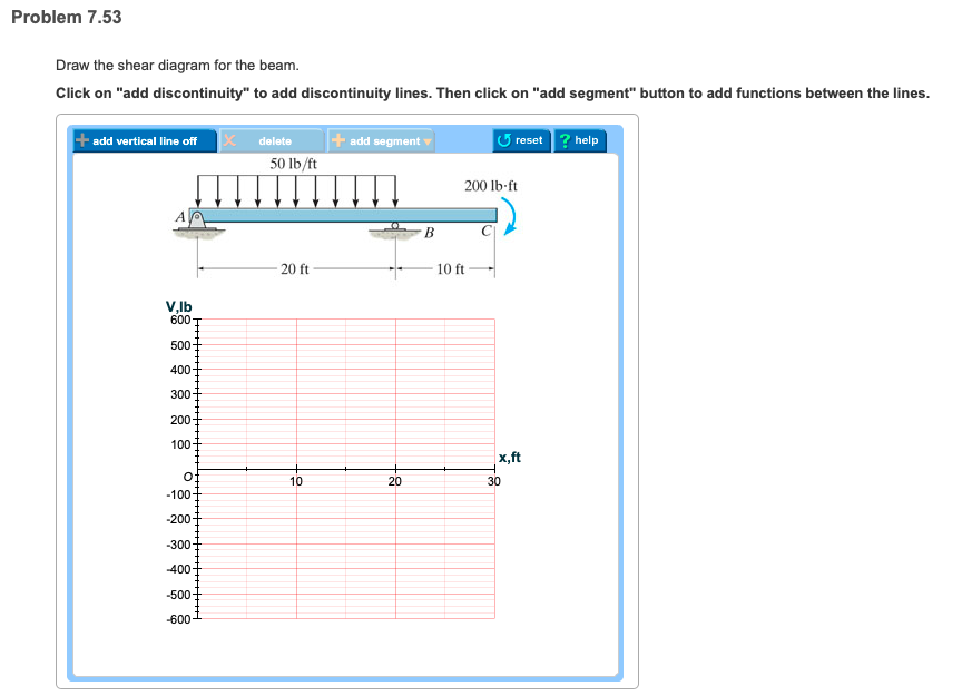
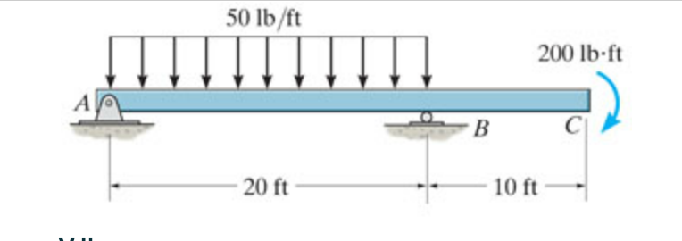
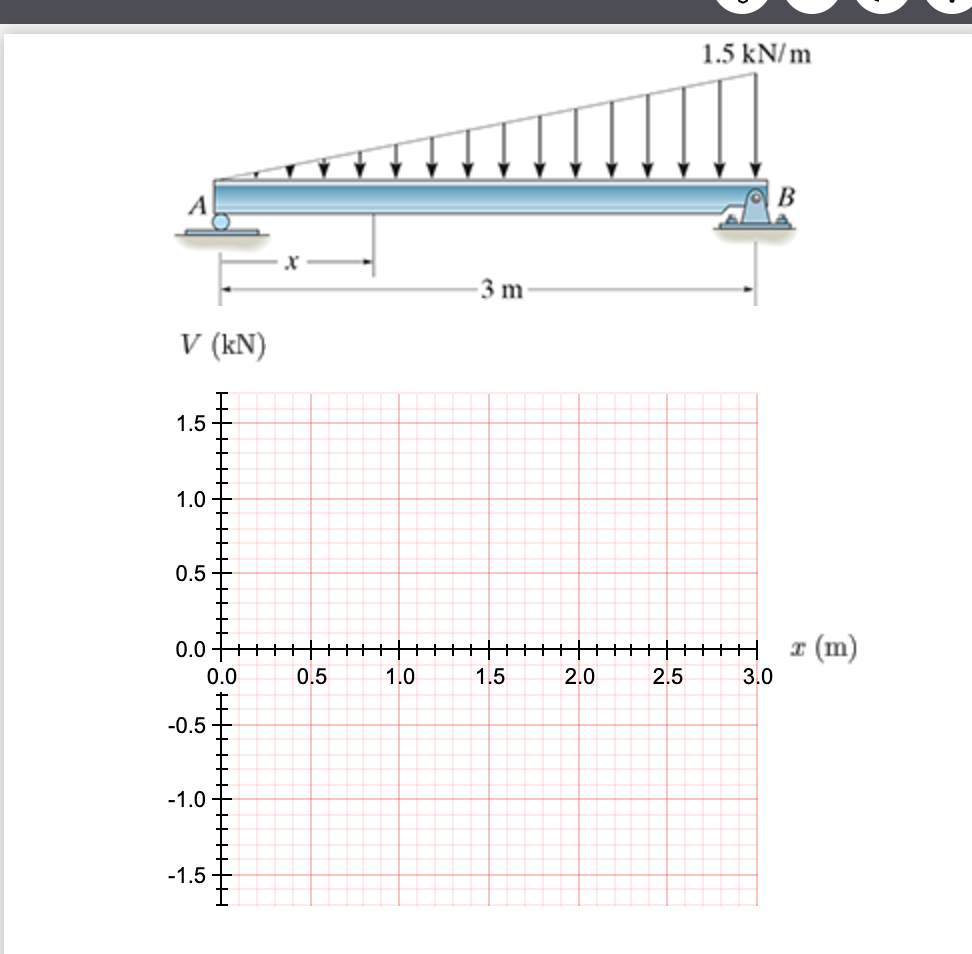
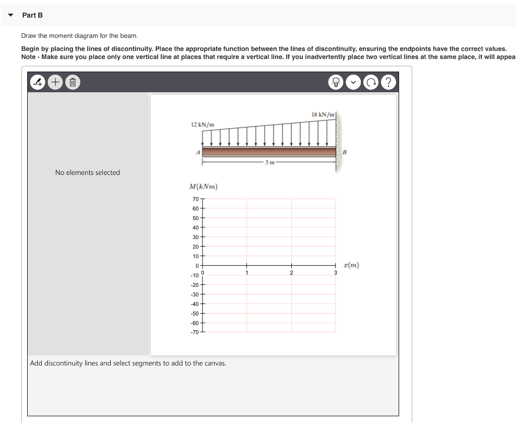
Draw the shear diagram for the beam. 7.53. Draw the shear and moment diagrams for the. beam. Indicate values at the supports and at the points. where a change in load occurs. B. 2 m. 2 m. 3 kN. A. 8 kN. F4-13. B. A. 4 m 2 m. 2 m. 6 kN. 6 kN · m. 8 kN. F4-14. 2 k / ft. A. 10 ft. 30 k· ft. F4-15. F4-14. Draw the shear and moment diagrams for the. beam. Indicate values at the ... Mechanical Engineering INTERNATIONAL EDITION---Engineering Mechanics: Statics, 14th edition (SI unit) Draw the shear and bending-moment diagrams for the beam. Prob. 7-53 more_vert Draw the shear and bending-moment diagrams for the beam. Prob. 7-53 For The Figure Below Draw Shear And Moment Diagrams Beam Study. Part A Draw The Shear Diagram For Beam B Moment Study. Solved Problem 7 80 Part A Draw The Shear Diagram For Chegg. Draw The Shear And Moment Diagram Of Beam Following Sign Convention 7 87 Study. Solved Problem 7 53 Part A Draw The Shear Diagram For Beam On 1 Transtutors. Problem 7.53 Part A Draw the shear diagram for the beam. Click on "add discontinuity" to add discontinuity lines. Then click on "add segment" button to add functions between the lines. Question: Problem 7.53 Part A Draw the shear diagram for the beam. Click on "add discontinuity" to add discontinuity lines.
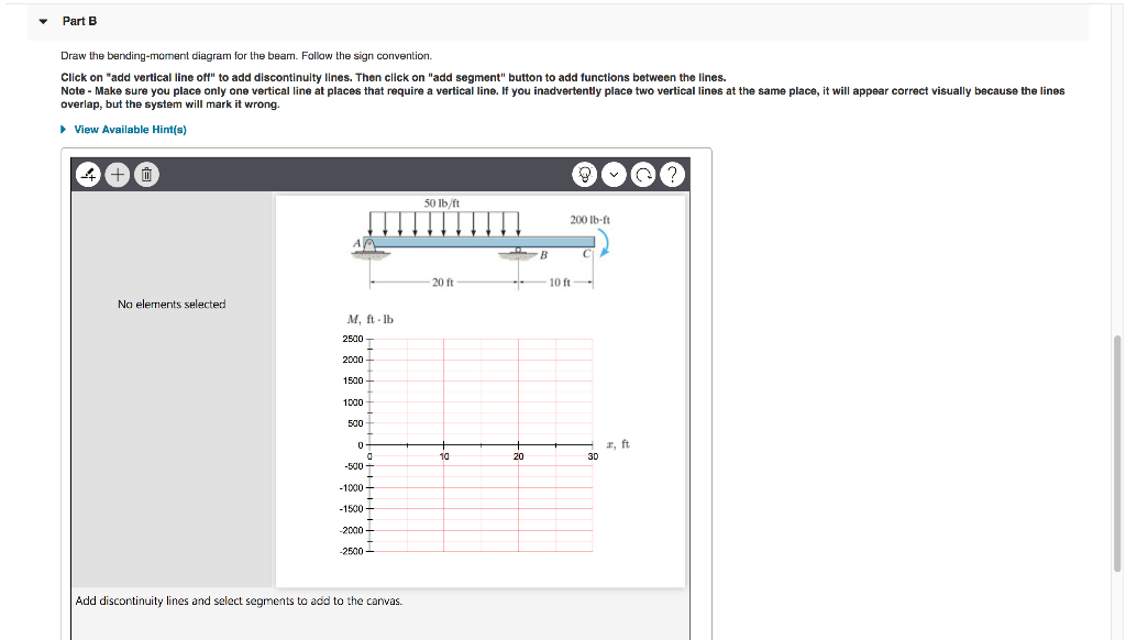
Solution Manual - Mechanics Of Materials 7th Edition, Gere, Goodno - ID:5c18dde35afdf. 00FM.qxd 9/29/08 8:49 PM Page i An Instructor’s Solutions Manual to Accompany ISBN-13: 978-0-495-24458-5 ISBN-10: 0-495-... draw free-body diagrams of bolt HJ and of the portion of the bolt located between the two planes (Fig. 1.19). Observing that the shear P in each of the sections is P = F∕2, the average shearing stress is τave = P F∕2 F = = A A 2A (1.10) H FC F K P K' L F L' P FD J (a) (b) Fig. 1.19 (a) Diagram of bolt in double shear; Transcribed text From Image:Problem 7.53 Part A Draw the shear diagram for the beam.Click on "add discontinuity" to add discontinuity lines. Then click on "add segment" button to add functions between the lines. add vertical line off add segment 0 lb/ft 200 lb ft 20 ft 0 ft Vlb 400 300 200 100 x,ft 30 10 100 Submit My Answers Give Ue beam from the left hand end and summing up the areas of shear force diagrams using proper sign convention. xThe process of obtaining the moment diagram from the shear force diagram by summation is exactly the same as that for drawing shear force diagram from load diagram.
Solved 7 53 Draw The Shear And Bending Moment Diagrams For Chegg ... Determine reactions draw shear bending moment diagrams beams shown figs p161 p165 using mo q33066256 duepapers 2 group solving problem draw the shear force and bending moment diagrams for beam shown u homeworklib draw the shear force and bending moment diagrams for beam shown ... this is a detailed example of shear and moment diagrams, i recommend skipping around to the sections shown below if you already have a feel for the subject:i... Problem 7.53 Part A Draw the shear diagram for the beam Click on "add discontinuity" to add discontinuity lines. Then click on "add segment" button to add functions between the lines. add segment reset ? help add vertical line off 50 lb/ft 200 lb ft 20 ft 10 ft V,lb 600 500 400 300 200 100 x,ft 10 20 30 -100 400 Submit My Answers Give Ujp Dmw the shellr andmomenl diagrams for the shaftTr,i,S\" T ,,lj .. 2kN · m 2ft - \"l' rob.7-4JS ,.2. T 2. T7-66. Draw the shear and moment diagrams for the · 7-69. Draw the shear and moment diagrams for thedouble O\"erhnng beam. simply supported beam.
Draw shear force and bending moment diagrams [SFD and BMD] for beam. Also determine maximum hogging bending moment. 30N/m 4m [Ans: Max. Hogging bending moment = 735 kNm] Exercise Problems 4m3m VM-79 80. 5kN 8. A cantilever beam of span 6m is subjected to three point loads at 1/3rd points as shown in the Fig. given below. Draw SFD and BMD for ...
7.79 draw the shear diagram for the beam. 1 k/ 1 k/ 1 k/ E A 15 10 15 [email protected]=20 Beam BMD (k-ft) The maximum positive and negative beam moments and shear forces are as follows. d. 79 draw the shear diagram for the beam. If there is an upward force ie a support then the sfd will start at this force above the x axis. 80 For the beam and loading shown, (a) draw the shear and bending ...

May 28, 2018 · The free-body diagram of the beam’s segment sectioned through the arbitrary points within these two regions are shown in Figs. b and c. Region , Fig. b (1) a (2) Region , Fig. c (3) a (4) The shear diagram shown in Fig. d is plotted using Eqs. (1) and (3). The location at which the shear is equal to zero is obtained by setting in Eq. (1).
Problem 7.53 Part A Draw the shear diagram for the beam. Click on "add discontinuity" to add discontinuity lines. Then click on "add segment" button to add functions between the lines. add vertical line off add segment 0 lb/ft 200 lb ft 20 ft 0 ft Vlb 400 300 200 100 x,ft 30 10 100 Submit My Answers Give Ue.

Draw the shear and moment diagrams for the beam : 2017320. 7-47. Draw the shear and moment diagrams for the beam (a) in terms of the parameters shown; (b) set P = 4 kN, a = 1.5 m, L = 3.6 m.

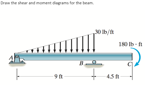
C A B 2 m 3 m 1.5 kN / m Prob. 7-52 7-53. Draw the shear and moment diagrams for the beam. 40 kN / m 20 kN 150 k N m A B C 8 m 3 m Prob. 7-53 7-54. Draw the shear and moment diagrams for the beam. 250 lb / ft 150 lb ft 150 lb ft A B 20 ft Prob. 7-54 7-55. Draw the shear and bending ...
Draw The Shear And Moment Diagrams For Beam 7 53. November 22, 2018 - by Arfan - Leave a Comment. 1 draw the shear and moment diagrams solution 1 draw the shear and moment diagrams. Solved 7 53 Draw The Shear And Bending Moment Diagrams F Chegg. Solved 7 53 Draw The Shear And Moment Diagrams For B Chegg.
Draw the Shear Force (SF) and Bending Moment (BM) diagrams. Solution: A Cantilever of length l carries a concentrated load W at its free end. Draw the Shear Force (SF) and Bending Moment (BM) diagrams. Consider the forces to the left of a section at a distance x from the free end.
Solved Problem 7 53 Part A Draw The Shear Diagram For Beam On 1 Transtutors. Ering Mechanics Statics Pages 351 400 Flip Fliphtml5. Part A Draw The Moment Diagram For Beam Follow Sign Convention B Shear Study. Solved Problem 7 55 Part A Draw The Shear Diagram For Bea On 1 Transtutors.
Then draw the shear force diagram sfd and bending moment diagram bmd. For drawing a bending moment diagram or bmd we use a positive sign for the sagging bending moment and a negative sign for the hogging bending moment as shown in the figure below. Follow the sign convention. B if p 20 kn and l 6 m draw the sfd and bmd for the beam.

Free online beam calculator for generating the reactions, calculating the deflection of a steel or wood beam, drawing the shear and moment diagrams for the beam. This is the free version of our full SkyCiv Beam Software. This can be accessed under any of our Paid Accounts, which also includes a full structural analysis software.

*7—56. Draw the shear and moment diagrams for the cantilevered beam. 300 1b - diagram of the beam's left through an arbitrary shown in fig. b will be to write the and mcnnent quations. The inœnsity the triangldar útributed load at of sectioning is — = 3333r Referring Fig. b , o V = {-300- 1b — +3001-0 The shear and diagrams shown in ...

7.6 Load vs. Shear vs. Bending moment Drawing Shear force and Bending moment diagrams for a beam can be simplified by using relationships between Load vs. Shear and Shear vs. Bending Moment. These relationships can be derived simply from statics as follows. Consider a small ∆x length of any beam carrying a distributed load.

7 53 Draw The Shear Diagram For Cantilevered Beam. Draw the shear and moment diagram bending moment diagram an overview forceoments in beams mcgraw solved problem 7 59 part a draw the bending moment diagram an overview. 329 6 1 Draw The Shear And Moment Diagrams For Shaft Bearings At A B Exert Only Vertical Reactions On.
Academia.edu is a platform for academics to share research papers.

Draw The Shear And Bending Moment Diagrams For Beam 7 53. Continuous beam design with moment 1 draw the shear and moment diagrams forceoments in beams mcgraw 1 draw the shear and moment diagrams problem solving in statics. Chapter 7 Solution Manual Ering Mechanics Statics 12th Edition By R C Hibbeler Docsity.
Academia.edu is a platform for academics to share research papers.
Draw the shear and moment diagrams for the beam : 2017321 7-48. Draw the shear and moment diagrams for the beam (a) in terms of the parameters shown; (b) set M 0 = 500 N · m, L = 8 m.

Refer to the indicated problem and draw complete shear and bending moment diagrams. Show ordinates at key points and indicate magnitude of shear and moment. Neglect the beam weight Calculate the shear and bending moment at 5 m and 10 m from the left...
The ratio of the area of the actual indicator diagram to the theoretical one is called diagram factor. Q. 5: Explain the working of any air standard cycle (by drawing it on P-V diagram) known to you. Why is it known as ‘Air standard cycle.’? (Dec–01) Or Draw the Diesel cycle on P-V coordinates and explain its functioning.


0 Response to "37 draw the shear diagram for the beam. 7.53"
Post a Comment