39 iron carbon phase diagram
Iron/Carbon Phase Diagram Iron shows a eutectic with Carbon allowing for a lower melting alloy Body Centered Tetragonal. 6. 7. 8 Carbon content can be reduced by reaction with oxygen and stirring. 9. 10 Eutectoid Steel Pearlite. 11 Time-Temperature-Transformation Diagram. 12 Time-Temperature-Transformation Diagram The iron-carbon diagram shows the sections in which the metal only has a certain condition. These are melt, Ferrite or Austenite. Other areas are characterised ...
The Iron–Iron Carbide (Fe–Fe3C) Phase Diagram In their simplest form, steels are alloys of Iron (Fe) and Carbon (C). The Fe-C phase diagram is a fairly complex one, but we will only consider the steel part of the diagram, up to around 7% Carbon.
Iron carbon phase diagram
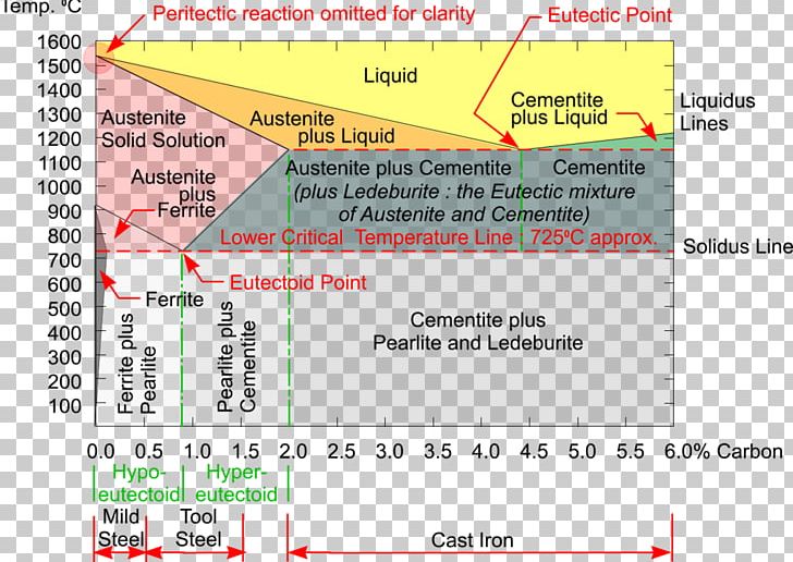
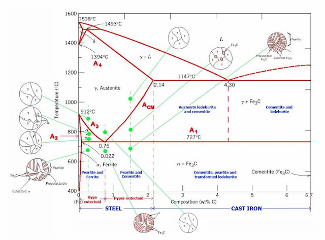
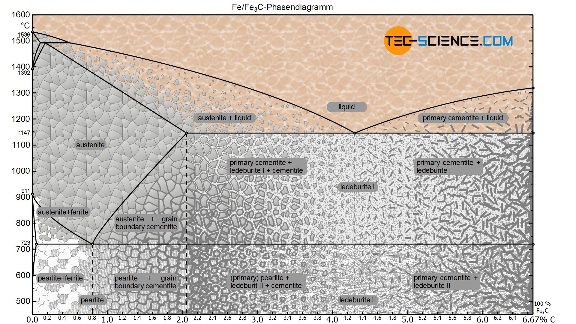
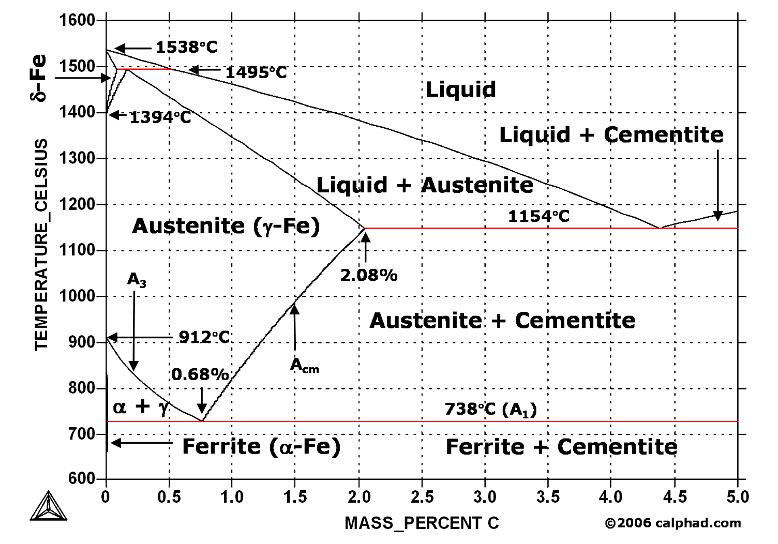
The Iron-Carbon Diagram: A map of the temperature at which different phase changes occur on very slow heating and cooling in relation to Carbon, is called Iron- Carbon Diagram. Iron- Carbon diagram shows - the type of alloys formed under very slow cooling, proper heat-treatment temperature and how the properties of steels and cast irons 1 Jun 2012 — Iron-carbon phase diagram describes the iron-carbon system of alloys containing up to 6.67% of carbon, discloses the phases compositions and ... This iron carbon phase diagram is plotted with the carbon concentrations by weight on the X-axis and the temperature scale on the Y-axis. The carbon in iron is an interstitial impurity. The alloy may form a face centred cubic (FCC) lattice or a body centred cubic (BCC) lattice. It will form a solid solution with α, γ, and δ phases of iron.
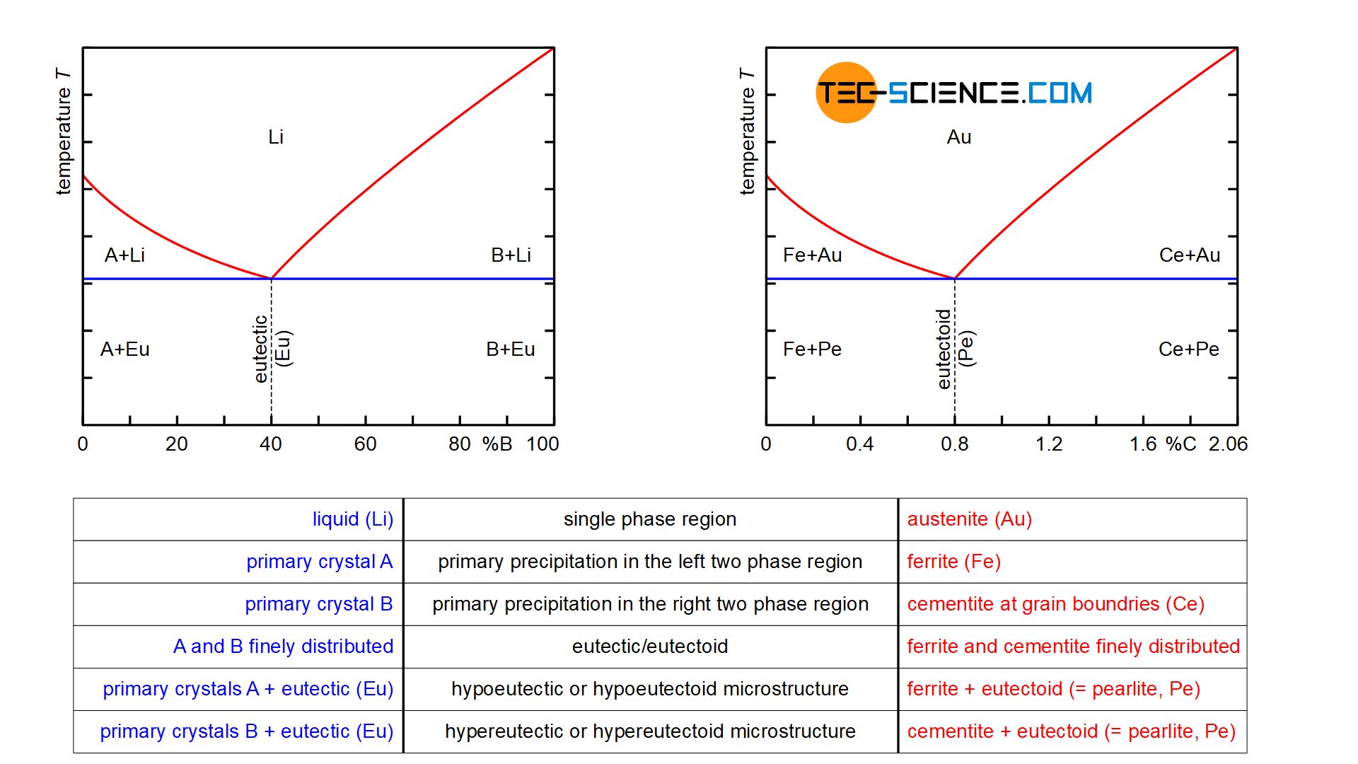
Iron carbon phase diagram. Iron-Carbon Phase Diagram with Detailed Explanation: If the percentage of the carbon is in the range of 0 to 2.11 % then it is called Steel and if the percentage of carbon is in the range of 2.11 to 6.67% then it is called Cast iron. As the carbon content increases, it produces more Iron-Carbide volume and that phase will exhibit high hardness. Simplified Iron-Carbon phase diagram austenite ↔ pearlite (mixture of ferrite & cementite) The Austenite to ferrite / cementite transformation in relation to Fe-C diagram. MICROSTRUCTURE OF AUSTENITE. MICROSTRUCTUREOF PEARLITE Photomicrographs of (a) coarse pearlite (b) fine pearlite . 3000X. Click here to download pdf notes NOW - http://bit.ly/3lggovpIron Carbon DiagramIron Iron Carbide DiagramIron Carbon Phase Diagram ExplanationIron Carbon Equ... Although it is heterogeneous, these phases behave like homogeneous pure bodies. Steel is between 0 and 2.06 mass percent of carbon. Cast iron is between 2.06 ...
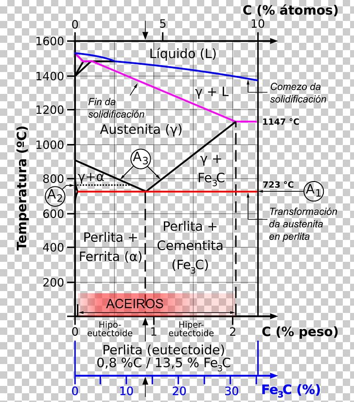
27 May 2019 — The Fe - C diagram (also called the iron - carbon phase or equilibrium diagram) is a graphic representation of the respective microstructure ... 27 Feb 2019 — Although it is heterogeneous, these phases behave like homogeneous pure bodies. Steel is between 0 and 2.06 mass percent of carbon. Cast iron is ...Date: 27 February 2019 Hypereutectoid steel: has a carbon content greater than the eutectoid 8 Example: Phase Equilibria For a 99.6 wt% Fe-0.40 wt% C at a temperature just below the eutectoid, determine the following a) composition of Fe 3C and ferrite (α) b) the amount of carbide (cementite) in grams that forms per 100 g of steel The iron-carbon system (steel and cast iron) MSE 2090: Introduction to Materials Science Chapter 9, Phase Diagrams 2 Component - chemically recognizable species (Fe and C
The Iron Carbon Phase Diagram · A1: The upper limit of the ferrite / cementite phase field (horizontal line going through the eutectoid point). · A2: The ... A. Phase Diagrams 1. Iron-Copper System The iron-copper phase diagram, taken from Hansen,3 is presented in Figure 1. Hansen3 also gives a thorough review of the work done on the system up to 1957. A review of more recent work, up to 1963 was done by . Elliott~ The most recent version of the phase diagram This iron carbon phase diagram is plotted with the carbon concentrations by weight on the X-axis and the temperature scale on the Y-axis. The carbon in iron is an interstitial impurity. The alloy may form a face centred cubic (FCC) lattice or a body centred cubic (BCC) lattice. It will form a solid solution with α, γ, and δ phases of iron. 1 Jun 2012 — Iron-carbon phase diagram describes the iron-carbon system of alloys containing up to 6.67% of carbon, discloses the phases compositions and ...
2
The Iron-Carbon Diagram: A map of the temperature at which different phase changes occur on very slow heating and cooling in relation to Carbon, is called Iron- Carbon Diagram. Iron- Carbon diagram shows - the type of alloys formed under very slow cooling, proper heat-treatment temperature and how the properties of steels and cast irons

Iron Carbon Phase Song Youtube
What Is The Difference Between An Iron Carbon And A Phase Diagram Quora

Iron Carbon Phase Diagram Google Search Metal Working Tools Metal Working Blacksmithing

Metastable Iron Carbon Fe C Phase Diagram
Iron Carbon Phase Diagram
Iron Carbon Phase Diagram Steel Cementite Png Clipart Angle Area Austenite Carbon Carbon Steel Free Png
1
Iron Carbon Phase Diagram Png Clipart Alloy Angle Area Austenite Carbon Free Png Download
Solved The Iron Carbon Phase Diagram Is Given Below Answer The Following Questions Based On The Graph A What S The Maximum Solubility In Wt Course Hero
Iron Carbon Diagrams

Scientific Net Publisher In Materials Science Engineering Iron Carbon Phase Diagram Credit Metallurgical Engineering Facebook
2

Gate Metallurgical Engineering Iron Iron Carbide Phase Diagram

Iron Carbon Phase Or Equilibrium Diagram Or Iron Carbide Diagram Mechstudies Com
Iron Carbon Phase Diagram Explained With Graphs
1

4 Iron Carbon Phase Diagram Download Scientific Diagram

Reading The Iron Carbon Phase Diagram Welding Hardfacing Cladding And Cutting Of Metals
Sketch And Explain The Iron Carbon Equilibrium Diagram Dieselship

Iron Carbon Phase Diagram In Their Simplest Form Steels Are Alloys Of Iron Fe And Carbon C The Study Of The Constitution And Structure Of Iron And Steel Start With The Iron Carbon

Iron Carbon Phase Diagram Drawing Iron Angle White Png Pngegg

115196164 Iron Carbon Diagram Pdf Document

The Iron Carbon Phase Diagram

Tpce Mech Books Iron Carbon Phase Diagram Or Equilibrium Diagram

Materila Science Engineering Iron Carbon Phase Diagram Slide 5
Vektor Stok Coloring Vector Ironcarbon Phase Diagram Tanpa Royalti 1516732415
Iron Carbon Phase Diagram
Iron Phase Diagram Roy Mech

115196164 Iron Carbon Diagram
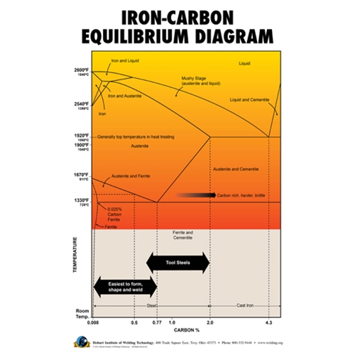
Iron Carbon Equilibrium Diagram Poster Hobart Institute Of Welding Technology

The Iron Iron Carbide Fe Fe3c Phase Diagram Ppt Download
Comparison Of Phase Transformations In Steels Tec Science
Iron Carbon Phase Diagram 12 Download Scientific Diagram

Gate Ese How To Remember Iron Carbon Phase Diagram Offered By Unacademy
Determination Of Microstructure And Phase Fractions In Steels Tec Science

Iron Carbon Phase Diagram

Iron Carbon Fe C Phase Diagram Ppt Download
Phase Diagram Iron Carbon Metallurgy For Dummies
0 Response to "39 iron carbon phase diagram"
Post a Comment