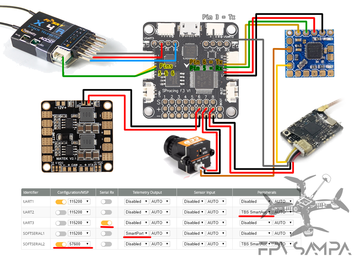
35 tbs unify pro wiring diagram
TBS UNIFY PRO 5G8 TBS UNIFY PRO 5G8 HV (RACE) Connection to DIY drone build Connection to TBS CORE products TBS UNIFY PRO 5G8 nano The UNIFY PRO 5G8 nano comes with pre tinned silicon wires for easy installation in your build. Technology showcase PitMode CleanSwitch SmartAudio SmartAudio LITE Declaration of Conformity Good practices You can find an overview of the complete wiring of a KISS CC here: TBS Unify Pro HV / Race. Currently the TBS Unify Pro HV is not yet supported, but we are working on that. unique tramp hv wiring diagram seriouslypro evo f3 quick setup sp; Unique tramp hv wiring diagram seriouslypro evo f3 quick setup sp racing xsr sbus with telemetry.
For this build I'm going with TBS unify Pro 32 nano which this board is designed for and of course a Crossfire Nano. One of the more trickier things I've had to solder as everything is so tiny. I have now soldered on the header pins for the Crossfire which will sit above the Unify VTX and ran the wires from the mounting board to the flight ...

Tbs unify pro wiring diagram
Instruction Diagram Receiver TBS Cross˜re Nano RX VTX ESC CH1 CH2 CH3 CH4 CH5 CH6 CH7 CH8 Band A 5865 5845 5825 5805 5785 5765 5745 5725 ... TBS UNIFY PRO 5G8 TBS UNIFY PRO 5G8 V G P B--SBUS_IN S.PORT GND +5v SBUS_OUT/CPPM + - F.Port www.geprc.com Hold the VTX Button for 2s Hold the VTX Button for 2s BOOT LED GEPRC V B 5 G GND 5V Buzz-LED +5V GND Tbs Unify Pro Wiring Diagram from www.kiwiquads.co.nz. Print the electrical wiring diagram off and use highlighters to be able to trace the signal. When you employ your finger or perhaps the actual circuit with your eyes, it’s easy to mistrace the circuit. A single trick that We use is to print out the same wiring picture off twice. TBS CORE PNP PRO installation diagram for TBS DISCOVERY PRO VTX 8 7 6 5 4 3 2 1 - + S PPM Gimbal Bottom link IMU/GoPro Roll Pitch VTX CAM 5V 12V 5V 12V Audio Video Gnd Pwr Pwr Gnd Video Audio GP Out Sel VTX2 Switch VTX2 Gnd Vbat Video Gnd Vcc Rx Tx UART Gimbal EzUHF RSSI Link Gimal Roll Gimbal Pitch Gimbal PPM Camera switch Analog RSSI Flight ...
Tbs unify pro wiring diagram. Tbs Crossfire Nano Rx Wiring Diagram. Omnibus F4 Revolt Osd Revoltosd Flightone Gps Tbs Unify Pro F4 Aio Flight Controller Micro Mamba F405 Crossfire Diversity Nano Raceflight Telemetry Crsf Unify Pro32 Betaflight. Black Sheep Tbs Crossfire Diversity Nano Rx Micro Dual Antenna Receiver Remote. More. Wiring diagram for Omnibus F3 Pro v2 with Tramp or TBS Unify. More. TBS Unifi Pro 5G8 HV, VTx, 25-800mW, RP-Sma. More. Unify Pro32 HV Settings Not Sticking. More. Crossfire Micro RX/Unify Pro HV (Race) wiring to CL Racing F4S FC. More. Diatone TBS UNIFY PRO32 NANO ADAPTOR BOARD. TBS Unify Pro HV horizontal lines on acceleration: sticksen: FPV Equipment: 96: Aug 07, 2018 11:23 AM: Discussion: Mounting TBS Unify Pro/Unify Pro HV SMA Pigtail Connector to Frame: MitchMan: Multirotor Drone Electronics: 1: Oct 13, 2016 08:37 PM: Discussion: TBS UNIFY PRO 5G8 HV strange blue screen: roachtron: FPV Equipment: 1: Sep 11, 2016 ... Please consider supporting me via Patreon at: https://www.patreon.com/thedroneracingengineerTBS Unify is an awesome video transmitter. Now there's an equally...
Asgard32 Wiring Guide. This guide is for the Asgard32 from Airbot including: 3 Receiver Types TBS Crossfire; Spektrum; FrSky; Smart Audio; Camera Control; Omnibus F4 with TBS Crossfire. A guide to wiring up TBS Crossfire Micro Receiver V2 to the Omnibus F4 Pro. This is probably my favorite usage of components and wring. VIII. How to set up VTX IRC Tramp and VTX TBS Unify Pro for CMS CANVAS mode on BetaFlight Set up Wiring Just wire the Tramp T (telemetry) wire or the TBS SmartAudio wire to a free hardware UART (TX) port. Configuration The up to date configurator supports easy configuration of the SmartAudio on the selected port. 1. Go to Ports tab 2. • OSD configuration using TBS SmartAudio 2.1 (via FC, TBS Crossfire/ Tracer or PNP PRO OSD) • LUA support for CRSF users • U.FL connector (Unify PRO32 nano) • MMCX connector (Unify PRO32 HV) • 1-3S input or 2-6S input with 5V output versions available • Improved noise filtering • Double noise filtering (Unify PRO32 HV) Reputation: 0. #1. 21-May-2020, 07:14 PM. I need some wiring help/verification. I have a TP3 that I want to replace some things on. I have a Betafpv 20A Toothpick board and a TBS nano receiver already hooked up. I want to add a Nano TBS Unify Pro32, Caddx Turtle V2 and a Fullspeed Buzzer. Betafpv FC/Fullspeed Buzzer: 5V/5V; GND/GND; Buzz-/BB-.
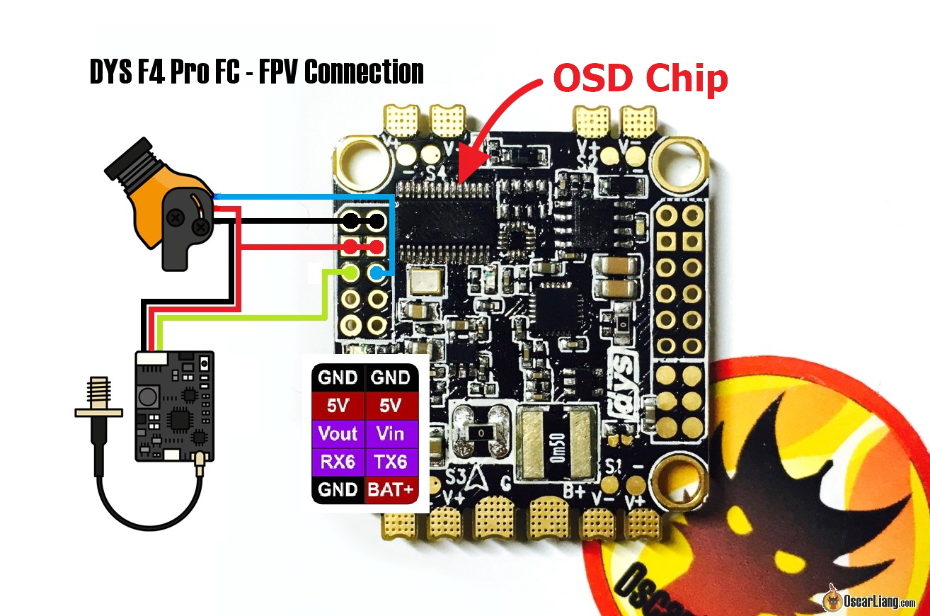
tbs unify pro hv gnd txi rxi xsr led (9 o o o o o) o o o o sbus sv gnd ppm 5v gnd pn2 5v gnd pn3 5v gnd pwm4 5v gnd ch4/rx6 ch6/tx6 gnd scl/tx3 sda/rx3 gno s.port breen u4 0 5v out video in gnd gnd vbat sj2 00000000000000 sck 0000 02 c24 agnd agnd o ran wut ram vin 06 reb o o u6 000 i i ilii usbi 0 esc o o o o gnd pwv4 o o o o o 00 rsso o u10 000 Tramp Vtx Wiring Diagram. Preliminary Operator's Manual The Tramp HV is a tiny, high power GHz Audio/Video transmitter designed for physical connection, using a TNR Wand. G = the Tramp has two Ground wires on the harness. Be sure to have your antenna connected any time you power the VTX or it will burn out. (23-Oct-2020, 12:15 AM) voodoo614 Wrote: Sounds like your Smartaudio is not working. Can you diagram your wiring or a clear photo? I'm not using smart audio, I'm using crossfire protocol. I can draw up a wiring diagram if you want, but I basically have two of my crossfire cables connected from my unify straight to my nano rx. Internet was lacking a proper wiring diagram for the DYS F4 Pro V2 TBS Unify Race, and a Runcam camera to the DYS Flight controller. The DYS F4 Pro V2 FC is a new AIO (all in one) flight controller that has been very I would have probably used wire harness for that reason.Jun 10, · DYS F4 Pro V2 Flight Controller Wiring advice Please! Hello ...
cameras today can take up to 6S voltage safely. Many vTX can take up to 6S voltage, however the TBS Unify Pro is one exception: it requires 5v maximum. Remember that the rated load of the 5v regulator on the Kakute F7 AIO is 2 amps. This means that the sum of the accessories you run from the regulator cannot exceed 2 amps.
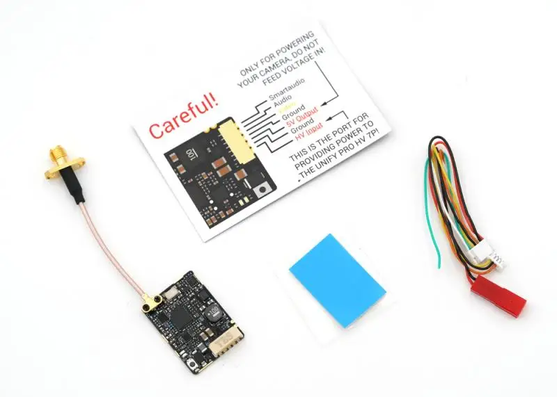
Asli Teamblacksheep Tbs Menyatukan Pro 5g8 Hv Sma Pitmode Smartaudio 2 6s 800mw Vtx Untuk Rc Drone Jarak Jauh Balap Parts Aksesoris Aliexpress
Pro V2 (5V only) This board was the original design. It is make for the Team BlackSheep Unify Pro V2 5V video transmitter. Because of the side pin out design of the Pro V2, you can have full access to the VTX without the use of the included pigtail plug. By soldering the Pro V2 to the mounting board via the 5 pads and 4 pin outs, you can solder ...
TBS has released new UNIFY PRO32 HV VTX.It is an updated version of the previous TBS UNIFY PRO HV with the boosted output power to 1000mW, improved the robustness by encasing everything in double-decker design, decreased the power consumption.This upgraded version has USB connector for firmware upgrades and other possible future features.UNIFY PRO32 HV has MMCX connector instead of the U.FL.
Tbs Unify Pro Wiring Diagram. Wiring Diagram 72 views. Double Light Switch Wiring Diagram Australia. Wiring Diagram 244 views. Hot Tub Wiring Diagram. Wiring Diagram 149 views. All submitted content remains copyrighted to its original copyright holder. Images are for personal, non commercial use.
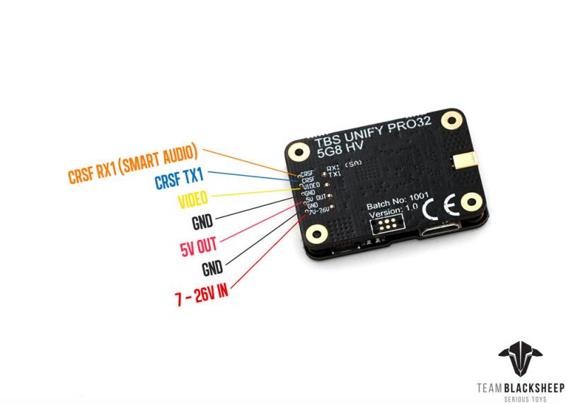
Crossfire Nano with TBS Unify Pro32 Nano. The 7 wires from the TBS Unify Pro 32 nano are as followed: white wire – From the VTX RX to Channel 4 on the crossfire nano; green wire – From the VTX TX to channel 3 on the crossfire nano; yellow wire – The video source for your VTX, usually on the flight controller, sometimes a direct feed to the camera.
Jul 13, 2019 · The red wire should go the the 9v pad instead of 5v pad which is shown in the Mamba wiring diagram? Yes, you have a HV version of the TBS Unify Pro32 which needs more then 5V so either connect the red wire to a 9V pad, or connect it to a VCC (LiPo voltage) pad. Your choice. GND to GND Yes. The white CRSF TX1?
Tbs unifi pro 5g8 hv, vtx, 25-800mw, rp-sma. Iflight succex f4 v2 mini with tbs unify pro 32 hv vtx wiring problem. Wiring mamba f40 to tbs unify pro32 hv and camera. Problems with unify pro hv race 2 (mmcx). Tbs unify evo. Tbs unify evo(sma) [tbs-unity-evo]. Wiring diagram for omnibus f3 pro v2 with tramp or tbs unify. Unify pro32 hv settings ...
TBS Unify Pro 5G8 V3 (RP-SMA) A video transmitter just for racers. 5g weight, 25 - 800mW output power (user adjustable). Cutting weight and flying far has never been this easy and affordable.Antenna Connector: RP-SMA Female Socket. The smallest and most powerful (800mW!) video transmitter the world has ever seen!
Wiring Diagram Includes. 1 x Diatone Mamba TBS Unify Pro32 Nano & Crossfire 20x20 Adapter Board; Additional Information. SKU: 12057: Manufacturer: Diatone: UPC (GTIN) 032733839015: Static Block: blank: Reviews Also Purchased. TBS Crossfire Nano Rx. $29.95. TBS Unify Pro Nano 5G8. $19.95. Lumenier QAV-R 2 Slam Freestyle Quadcopter Frame. $74.99 ...
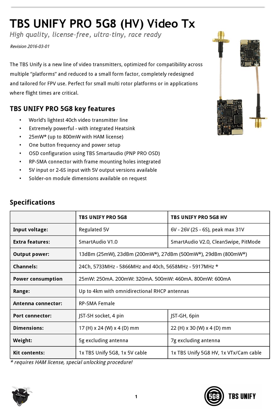
Page 1 TBS UNIFY PRO 5G8 (HV) Video Tx High quality, license-free, ultra-tiny, race ready vtx Revision 2017-08-15 The TBS UNIFY is a new line of video transmitters, optimized for compatibility across multiple “platforms” and reduced to a small form ...; Page 2: Specifications Specifications TBS UNIFY PRO V2 5G8 TBS UNIFY PRO 5G8 HV TBS UNIFY PRO HV RACE Input voltage: Regulated 5V 6V to ...
Unify to these or later versions. Updating In order to update your Unify Evo you need the TBS Agent X, which you can download from the TBS shop . To update your VTX, connect it by the USB-port and run the update by Agent X. For detailed instructions on how to use Agent X, have a look at the Agent X manual. 5
I have a tbs unify Pro HV and Foxxeer T-Rex and am using Hobbywing G3 stack. The vtx will accept 2-6S and camera 4.5-16 volts. I have wired up several air unit and Caddx vista to HW G3 stack but not analog. Here’s a diagram and I see several ways to wire up the FPV system.Directions with vtx and cameras don’t mention using FC and I see ...
Is there an updated wiring diagram for this mod? The TBS UNIFY PRO 5G8 uses only 5V. The picture seams to indicate that it the transmitter is drawing power from the serial port output. I'm also planning on using a Fat Shark CMOS camera which is limited to 5V as well.
TBS Unify Pro HV vtxtable bands 5 vtxtable channels 8 vtxtable band 1 BOSCAM_A A FACTORY 5865 5845 5825 5805 5785 5765 5745 5725 vtxtable band 2 BOSCAM_B B FACTORY 5733 5752 5771 5790 5809 5828 5847 5866 vtxtable band 3 BOSCAM_E E FACTORY 5705 5685 5665 5645 5885 5905 5925 5945 vtxtable band 4 FATSHARK F FACTORY 5740 5760 5780 5800 5820 5840 ...
With the TBS UNIFY PRO32 HV we have boosted the output power, improved the robustness, decreased the power consumption, added capability for insane features and perfected the way it is installed in your multirotor. In a nutshell, it's the most comprehensive, future proof, highest quality and overall best HV VTx ever made.
TBS CORE PNP PRO installation diagram for TBS DISCOVERY PRO VTX 8 7 6 5 4 3 2 1 - + S PPM Gimbal Bottom link IMU/GoPro Roll Pitch VTX CAM 5V 12V 5V 12V Audio Video Gnd Pwr Pwr Gnd Video Audio GP Out Sel VTX2 Switch VTX2 Gnd Vbat Video Gnd Vcc Rx Tx UART Gimbal EzUHF RSSI Link Gimal Roll Gimbal Pitch Gimbal PPM Camera switch Analog RSSI Flight ...
Tbs Unify Pro Wiring Diagram from www.kiwiquads.co.nz. Print the electrical wiring diagram off and use highlighters to be able to trace the signal. When you employ your finger or perhaps the actual circuit with your eyes, it’s easy to mistrace the circuit. A single trick that We use is to print out the same wiring picture off twice.
Instruction Diagram Receiver TBS Cross˜re Nano RX VTX ESC CH1 CH2 CH3 CH4 CH5 CH6 CH7 CH8 Band A 5865 5845 5825 5805 5785 5765 5745 5725 ... TBS UNIFY PRO 5G8 TBS UNIFY PRO 5G8 V G P B--SBUS_IN S.PORT GND +5v SBUS_OUT/CPPM + - F.Port www.geprc.com Hold the VTX Button for 2s Hold the VTX Button for 2s BOOT LED GEPRC V B 5 G GND 5V Buzz-LED +5V GND










0 Response to "35 tbs unify pro wiring diagram"
Post a Comment