36 payne heat pump wiring diagram
Payne Heat Pump Wiring Diagram. Payne Heat Pump Wiring Diagram from www.gridgit.com. Print the wiring diagram off plus use highlighters to trace the signal. When you make use of your finger or perhaps the actual circuit with your eyes, it is easy to mistrace the circuit. 1 trick that We 2 to printing a similar wiring plan off twice. Installation Instructions. PH15NB. SPLIT--SYSTEM HEAT PUMP. WITH R--410A REFRIGERANT. 1--1/2 -- 5 TONS. SAFETY CONSIDERATIONS.10 pages
View and Download Payne PH3Z024 installation instructions manual online. PH3Z 13 Seer Single-Packaged Heat pump System with R-22 Refrigerant Single And ...
Payne heat pump wiring diagram
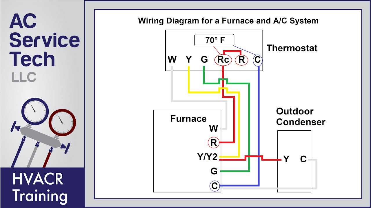
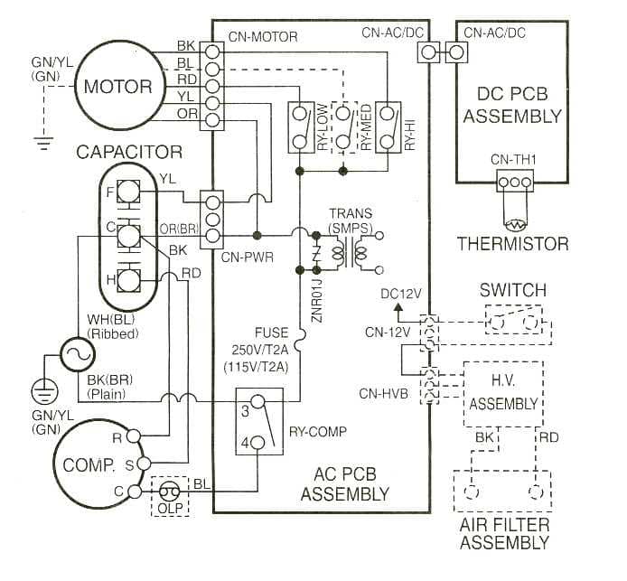
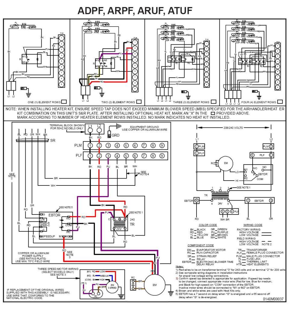
SCHEMATIC DIAGRAM SINGLE SUPPLY CIRCUIT ... IF WIRE CRIMP IS REMOVED AN EMERGENCY HEAT RELAY IS REQUIRED. ... HEAT PUMP HEAT. ONLY OPERATING. Payne Heating & Cooling.Heat pump thermostat wiring - A typical wire color and terminal diagram. As shown in the diagram, you will need to power up the thermostat and the 24V AC power is connected to the R and C terminals. The color of wire R is usually RED and C is BLACK. C is known as the common terminal. Heat pump thermostat wiring - A typical wire color and terminal diagram. As shown in the diagram, you will need to power up the thermostat and the 24V AC power is connected to the R and C terminals. The color of wire R is usually RED and C is BLACK. C is known as the common terminal. These two connections will ensure that there is power to the thermostat that you are operating.
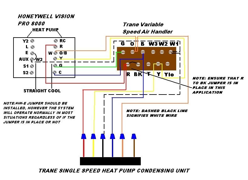
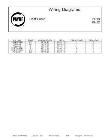
Payne heat pump wiring diagram. Diagram payne heat pump wiring full version hd quality thermostat diagrams ac unit i have a model ph10ja036 f 5 wires coming to the at hook up are furnace fan pf1mna036 that is acting oddly mostly it works fine but on occasion outside compressor chart 101 nest for system schematic 208 single phase installation and service manuals heating… Read More » HEAT PUMP (CONTROL g--wiring Layout (Cooling and Air Conditioning l-Stage Neat) Unit FAN COIL (CONTROL) THERMOSTAT HEAT PUMP CONTROL R R _G R _G []- C C W3 ... Payne Heat Pump Wiring Diagram 8 Wire from contentgrid.homedepot-static.com Print the wiring diagram off plus use highlighters to trace the signal. When you make use of your finger or perhaps the actual circuit with your eyes, it is easy to mistrace the circuit. 1 trick that We 2 to printing a similar wiring plan off twice. click on that, on the next page that opens click on.Back To Payne Heat Pump Model: PH12 Payne Wiring Diagrams Information for PH10 PH12 Series Heat Pump. AC Heat Pump with Variable Speed Air Handler and Two Stage Electrical Backup Heat Control Wiring Some AC Systems will have a blue wire with a pink stripe in place of the yellow or Y wire.
I have a Payne heat pump model PH10JA036-F I have 5 wires coming to the thermostat. The wires at the pump hook up are marked C O Y2 and W2 plus the green for the fan. ... This is a standard heat pump wiring diagram.The only difference you should have is the RTH 7600 doesn't use the Common and it has an AUX instead of W2,(The jumper from Aux ... Payne heat pump wiring diagram 78.iq-radiothek.de PH14NB . Payne offers dependable, affordable and energy efficient, residential heat pumps, heating and cooling, efficient HVAC systems. Payne ph3zna030000aa package unit installation guide manualzz diagram ac wiring full version hd quality and service manuals for heating heat pump air conditioning equipment brands p s free manual thermostat chart 101 i have a model ph10ja036 f 5 wires coming to the at hook up are towing bryant tstatbhpdf01 3 ton by carrier 15 seer r410a split… Read More » Wiring Diagram. 16 SEER 2---Stage. Split---System Heat Pump. With R---410A Refrigerant. 2 To 5 Tons (024---060) ... E2012 Payne Heating & Cooling Systems D.
Description: Payne Wiring Diagram Payne Heat Pump Wiring Diagram Wiring in Payne Heat Pump Wiring Diagram, image size 1023 X 679 px, and to view image details please click the image.. Here is a picture gallery about payne heat pump wiring diagram complete with the description of the image, please find the image you need. Heat pump thermostat wiring - A typical wire color and terminal diagram. As shown in the diagram, you will need to power up the thermostat and the 24V AC power is connected to the R and C terminals. The color of wire R is usually RED and C is BLACK. C is known as the common terminal. These two connections will ensure that there is power to the thermostat that you are operating. Payne Heating & Cooling.Heat pump thermostat wiring - A typical wire color and terminal diagram. As shown in the diagram, you will need to power up the thermostat and the 24V AC power is connected to the R and C terminals. The color of wire R is usually RED and C is BLACK. C is known as the common terminal. SCHEMATIC DIAGRAM SINGLE SUPPLY CIRCUIT ... IF WIRE CRIMP IS REMOVED AN EMERGENCY HEAT RELAY IS REQUIRED. ... HEAT PUMP HEAT. ONLY OPERATING.
W1 W2 E Hvac School
Thermostat Wiring To A Furnace And Ac Unit Color Code How It Works Diagram Youtube
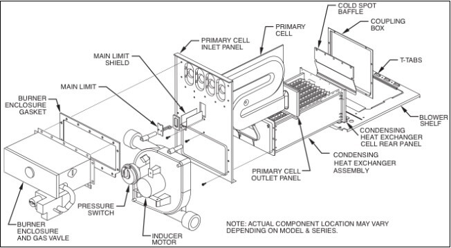
Carrier Heat Exchanger Primary And Secondary Replacement Process

Home Garden Oem Carrier Bryant Payne Heat Pump Defrost Sensor L65f 33 Hh18ha279 Hh18ha279a Ysseglobal Org
Wiring Diagrams Expressoverstock Com

Coleman Electric Wiring Diagram Rate Wiring Diagram Payne Ac Unit Inspirationa Payne Electric Thermostat Wiring Electrical Diagram Diagram

Payne Heat Pump Prices And Reviews 2021

New Installation Wiring Heat Pump And Aux Heat R Ecobee
Installation And Service Manuals For Heating Heat Pump And Air Conditioning Equipment Brands P S Free Manual Downloads

Heat Pump Thermostat Wiring Chart Diagram Quality 101
Wiring Diagrams Manualzz

Payne Heat Pump Package Unit Wiring Diagram Its Your Curriculum Vitae

File Ventilation Unit With Heat Pump Ground Heat Exchanger Png Wikimedia Commons

I Have A Payne Ac Unit And A Carrier Air Handler They Were Installed Prior To New Electrical Service To The House And

Unique Trane Heat Pump Thermostat Wiring Diagram Thermostat Wiring Trane Heat Pump Electrical Diagram

I Need A Basic Wiring Diagram For An Old Ruud Heat Pump Air Handler T Stat My System Has Been Complete Disconnected And
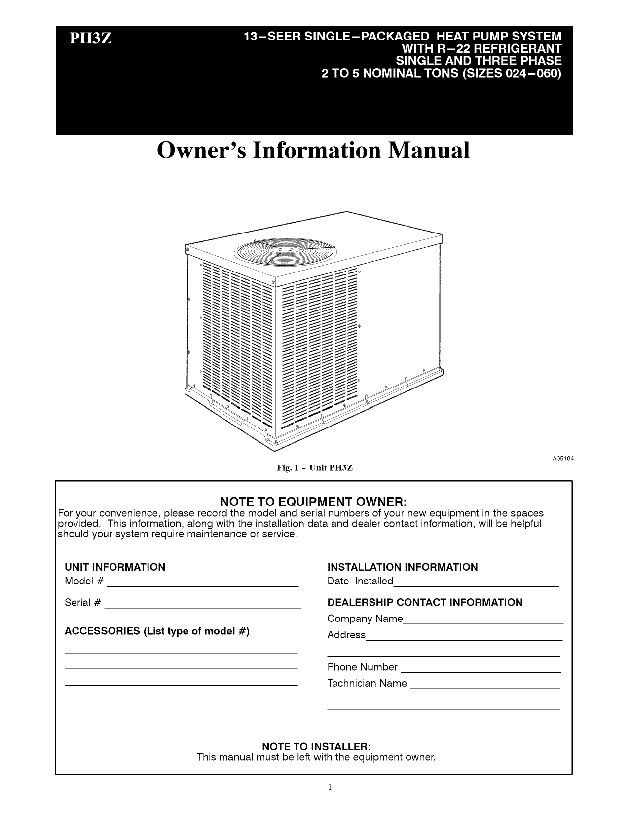
Payne Ph3zna030000aa Package Unit Owner S Manual Manualzz
Honeywell Thermostat
Installation And Service Manuals For Heating Heat Pump And Air Conditioning Equipment Brands P S Free Manual Downloads

Payne 1 5 Ton 14 Seer Residential Heat Pump Condensing Unit Dense Grille Carrier Hvac
Wiring Diagrams
Installation And Service Manuals For Heating Heat Pump And Air Conditioning Equipment Brands P S Free Manual Downloads
Heatcoolparts Com Heating And Air Conditioning Parts Furnace Parts Heating Parts
How Do I Identify The C Terminal On My Hvac Home Improvement Stack Exchange
2
My Furnace Is A Payne R Nest

Payne Heat Pump Wiring Diagram Thegirlintheelegantscarf

I Have A Payne Heat Pump Model Ph10ja036 F I Have 5 Wires Coming To The Thermostat The Wires At The Pump Hook Up Are
Air Handler Fan Wont Shut Off Under Repository Circuits 39052 Next Gr

Hvac Parts Accessories Oem Carrier Bryant Payne Compressor Wiring Harness Plug 312906 404 312906 440 Home Improvement

Icp Heil Tempstar Defrost Control Board 1174185 Hk32ea003 Heat Pump Circuit 83 98 Picclick Uk

I Bought A 15 Kw Heat Strip For Carrier Bryant Payne Heat Pump Package Units Part Wgs1502h And I Lost The Directions

Payne Heat Pump Prices And Reviews 2021
1
Hvac Talk Heating Air Refrigeration Discussion
Wiring Diagrams
0 Response to "36 payne heat pump wiring diagram"
Post a Comment