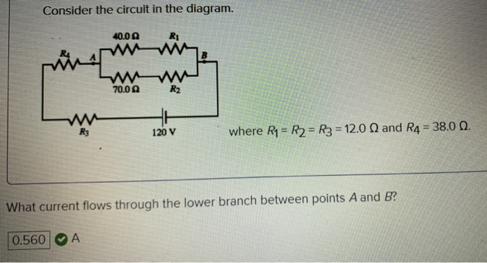
40 consider the circuit in the diagram
Question 6: (10%) Consider the following 2-to-1 MUX built using transmission gates as shown in class. The ~pickX signal is generated from an inverter which has a delay of 2 time units. Look at the given timing diagram and draw the waveform for Out from beginning to end. Is there any period of time when Out isn’t well defined? Example IV-1. Consider the circuit shown below, where R1 = 3.00 Ω, R2 = 10.0 Ω, R3 = 5.00 Ω, R4 = 4.00 Ω, and R5 = 3.00 Ω. (a) Find the equivalent resistance of this circuit. (b) If the total power supplied to the circuit is 4.00 W, find the emf of the battery. + − E R1 R2 R3 R4 R5 Solution (a): We have to reduce this circuit in steps ...
Everything in the circuit will remain the same. The current in the circuit and the voltage, everything will remain the same. So let's go ahead and do that. So what we'll do is I'll keep the rest of the circuit as it is. So let's draw the rest of the circuit as it is, but replace this combination with a single resistor of eight ohms. There it is.

Consider the circuit in the diagram
Consider the combination circuit in the diagram at the right. Use the diagram to answer the following questions. (Assume that the voltage drops in the wires themselves in negligibly small.) Consider the following circuit diagram: 20 kΩ 3 V 2 V 15 V 20 ΚΩ 40 k2 R 160 k2 -15 V What is the resistance R value to obtain output voltage v, equals to - 5.625 V ? (a) 20 kN (b) 80 kN (c) 160 kN (d) does not exist An electric potential diagram is a conceptual tool for representing the electric potential difference between several points on an electric circuit. Consider the circuit diagram below and its corresponding electric potential diagram. The circuit shown in the diagram above is powered by a 12-volt energy source.
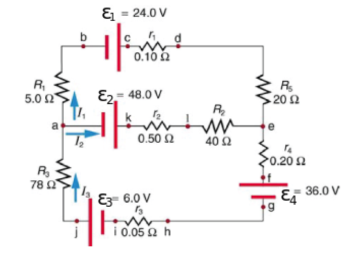
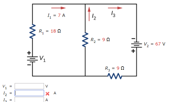
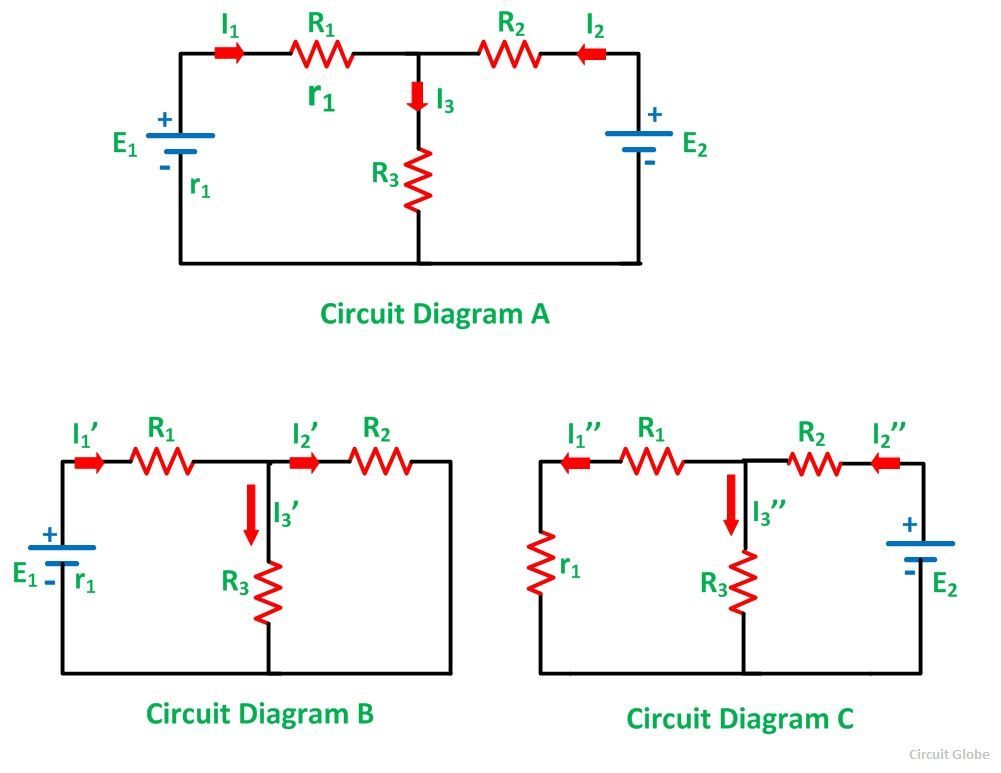
Consider the circuit in the diagram. Consider the circuit in the diagram, with sources of emf listed below. Randomized Variables. ℰ1 = 21 V. ℰ2 = 49 V. ℰ3 = 9.5 V. ℰ4 = 39 V. a) Find I 1 in amps. B) Find I 2 in amps. C) Find I 3 in amps. A PlusPhysics: Circuits-Circuit Analysis On the diagram above, use thc appropriate circuit symbol to indicate a correct placement of a voltme- ter to determine the potential difference across the circuit. What is the total resistance of the circuit? 1. 0.42 Q 2. 2.4Q 3. 5.00 4. ton The diagram below represents an electric circuit con- (b) The circuit diagram shows the shows battery as an emf source and an internal resistor. The two emf sources have identical emfs (each labeled by ) connected in parallel that produce the same emf. Consider the Kirchhoff analysis of the circuit in (Figure) (b). In the circuit diagram, 4 diodes are arranged in the form of a bridge. The transformer secondary is connected to two diametrically opposite points of the bridge at points A & C. The load resistance R L is connected to bridge through points B and D. Full Wave Bridge Rectifier - Circuit Diagram with Input and Output Wave Forms
The circuit diagram of half-wave rectifier is shown below • Rectifier: Rectifier is a circuit that converts AC voltage into DC voltage DC is a constant voltage signal. Diode rectifiers convert the AC into unidirectional pulsating signal (not pure DC) Assume ideal diode Cut-in voltage=0 Volts When forward biased: Acts as short circuit When ... 46.7 OV Consider the circuit in the diagram. 20 where R4 = R2 = R3 = 12.0 and R4 = 38.0 N. What current flows through the upper branch between points A and B? Analyzing a resistor circuit with two batteries. Transcript. An example of simplifying a seemingly complicated resistor circuit. Created by Willy McAllister. Google Classroom Facebook Twitter. Email. Ohm's law and circuits with resistors. Introduction to circuits and Ohm's law. Basic electrical quantities: current, voltage, power. Consider the circuit shown in the diagram below. The battery has a voltage V = 12.0 V and the resistors have the following values. R = 5,13; R2 - 10.26 0; R3 = 25.65 ; R. - 15.390 How much current flows through each of the four resistors? А 12 13 14 A A उस www w www w www R: Question: Consider the circuit shown in the diagram below. The ...
A kitchen in North America has three appliances connected to a 120 V circuit with a 15 A circuit breaker: an 850 W coffee maker, a 1200 W microwave oven, and a 900 W toaster. Draw a schematic diagram of this circuit. Which of these appliances can be operated simultaneously without tripping the circuit breaker? PHY2049: Chapter 27 33 Circuit Problem (1) ÎThe light bulbs in the circuit are identical.What happens when the switch is closed? a) both bulbs go out b) the intensity of both bulbs increases c) the intensity of both bulbs decreases d) nothing changes Before switch closed: V a = 12V because of battery. V b =12 because equal resistance divides 24V in half. Consider the compound circuit shown above. The three bulbs 1, 2, and 3 - represented as resistors in the diagram - are identical. Which of the following statements are true? Select two correct answers. (A) Bulb 3 is brighter than bulb 1 or 2. This abruptly reduces the number of logic gates or integrated circuits to perform the logic function since the multiplexer is a single integrated circuit. In this kind of applications, multiplexers are viewed as logic function generators. For example consider the below logic diagram to implement the ex-OR function of three inputs.
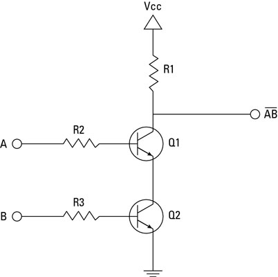
Use Transistors To Build A Nand Gate
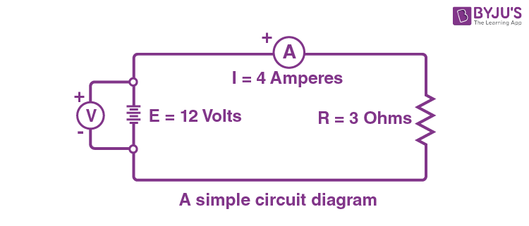
A simple circuit is one in which there is a single voltage source and a single resistance. One statement of Ohm's law gives the relationship between current I, voltage V, and resistance R in a simple circuit to be I = V R I = V R. Resistance has units of ohms (Ω), related to volts and amperes by 1 Ω = 1 V/A.
Solved Consider The Circuit In The Diagram 40 00 Rawws W Chegg Com
Let’s consider a sentence, such as ( P Q). Its circuit diagram is just: This is easy enough. Using this diagram, we can easily calculate the ‘output’ truth value, for the whole sentence, for any pair of ‘input’ truth values, one for each atomic sentence P and Q. For example, if P and Q are both true then we get: This fact is shown on ...

Consider The Circuit Shown In The Diagram Find The Current In 3w Resistor Electricity Forum
Consider the circuit in the diagram. Current I1 = 2.50 A Find the values of (a) I2, (b) I3, and (c) R3,. Step-by-step solution. Step 1 of 5.
Solved Consider The Circuit Depicted In The Diagram If The Chegg Com
Let's now consider the circuit shown on Figure 3 where a capacitor of capacitance C is connected to a time varying voltage source v(t). i(t) v(t) C v +-Figure 3. Fundamental capacitor circuit If the voltage v(t) has the form
Answered Consider The Following Circuit Diagram Bartleby
Consider the circuit below: ... On a circuit diagram, an ammeter is shown as an A in a circle. Again, the ammeter acts as a resistor, so to minimize its impact on the circuit it must have a small resistance relative to the resistance of the resitor whose current is being measured.
Circuit Diagram And Its Components Explanation With Circuit Symbols
Consider the circuit in the diagram. Given: I1 = 2.50 A, ℰ1 = 30.0 V, ℰ2 = 9.00 V, R1 = 8.00 Ω, and R2 = 5.00 Ω. Find the values of. I2, I3, and R3.

Bridge Rectifiers What Is It Circuit Diagram Working Principle Electrical4u
This circuit is sufficiently complex that the currents cannot be found using Ohm's law and the series-parallel techniques—it is necessary to use Kirchhoff's rules. Currents have been labeled I 1, I 2, and I 3 in the figure and assumptions have been made about their directions. Locations on the diagram have been labeled with letters a ...

The Word Circuit Means Closed Path Ppt Video Online Download
Diagram A 12 v Diagram B Consider the following two diagrams of series circuits. For each diagram, use arrows to indicate the direction of the conventional current. Then, make comparisons of the voltage and the current at the designated points for each diagram. Diagram A or VB X Vc or or or =) Diagram B VA < or VB < Vc or or or 5. 6.
Solved Consider The Circuit Shown Below Find V1 In V I2 Chegg Com
circuit diagram as follows: In this circuit, both capacitors would have the same potential difference as the battery. ΔV bat = ΔV 1 = ΔV 2 Plus, we can say that the charges on either plate are equal to the total that passes through the battery. Q Tot = Q 1 + Q 2. Capacitors
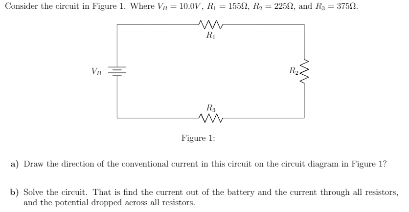
Solved Consider The Circuit In Figure 1 Where Vb 10 0v Chegg Com
Transcribed image text: Consider the circuit in the diagram, with sources of emf listed below. Randomized Variables epsilon_1 = 26 V epsilon_2 = 43 V ...
Solved Consider The Circuit Shown In The Figure Chegg Com
Consider the diagram of a circuit containing one cell connected to 2 bulbs in series with a switch that is closed. 4.1 Copy the diagram onto your answer sheet and draw in an ammeter that measures the current through the wire at A. (1) 4.2 The current at A was found to be 0,6 A. What is the current at point C?

Question Video Determining The Circuit Diagram That Represesnts The Ammeter Nagwa
In The Circuit Diagram Shown R 10 Ohm L 5 Mh E V And I 1 A Cur Is Decreasing At Rate Of 3 S Then Va Vb. For The Circuit Shown In Diagram Below Studyrankersonline. Sensors Free Full Text Intelligent Ball Bearing Fault Diagnosis Using Fractional Lorenz Chaos Extension Detection Html. In the circuit diagram shown below v a and vb are potentials at ...
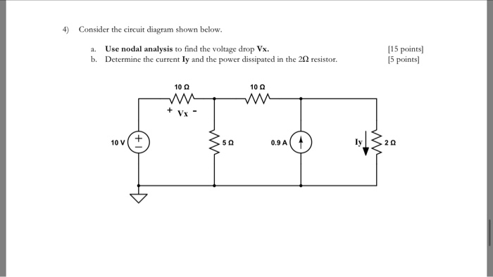
Solved 4 Consider The Circuit Diagram Shown Below A Use Chegg Com
Transcribed image text: (10%) Problem 5: Consider the circuit diagram depicted in the figure 0.5 Ω R2 2.5 Ω /2 R 1.5Ω 0.5 Ω 50% Part (a) what equation do ...
Answered Consider The Following Circuit Diagram Bartleby
Quantum circuit diagram conventions. In a circuit diagram, each solid line depicts a qubit, or more generally, a qubit register. By convention, the top line is qubit register 0 0 and the remainder are labeled sequentially. Operations are represented by quantum gates. The term quantum gate is analogous to classical logic gates.
Circuit Diagram Simple Circuits Electricity And Circuits Don T Memorise Youtube
• Proper use of the alternate gate symbols in the circuit diagram can make the circuit operation much more easy to understand • E.g., the two circuits on the right are equivalent • However circuit (a) does notHowever, circuit (a) does not facilitate an understanding of how the circuit function • Circuit (b) is easy to
6 3 Kirchhoff S Rules Introduction To Electricity Magnetism And Circuits
A current to voltage converter is an op amp circuit which accepts an input current and gives an output voltage that is proportional to the input current. The basic current to voltage converter is shown on Figure 5. This circuit arrangement is also called the transresistance amplifier. Iin R Vout N1 Figure 5. Current to voltage converter

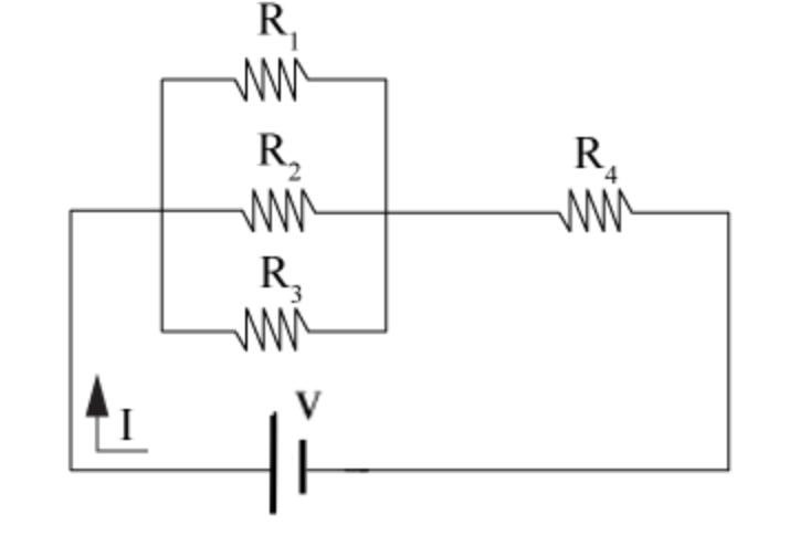
The Circuit Diagram Given Below Shows The Combination Of Three Resistors R1 R2 And R3 Find I Total Resistance Of The Circuit Ii Total Current Flowing In The Circuit Iii Total P D
The circuit diagram of the ‘Q’ meter is shown below. It is designed with an oscillator that uses the frequency that ranges from 50 kHz – 50 MHz. and provides current to a shunt resistance ‘Rsh’with 0.02 ohms value. Here thermocouple meter is used to calculate the voltage across the shunt resistance whereas an electronic voltmeter is ...
Electric Circuit
For example, consider the CMOS inverter: For more complex digital CMOS gates (e.g., a 4-input OR gate), we find: 1) The PUN will consist of multiple inputs, therefore requires a circuit with multiple PMOS transistors. 2) The PDN will consist of multiple inputs, therefore requires a circuit with multiple NMOS transistors. V DD A Y=A PUN PDN
Gate Cse 2006 Question 37 Gate Overflow
Consider the circuit in the diagram, (a) Draw the simplest equivalent circuit and label the values of the resistor(s). (b) What current flows from the ...
Solved Consider The Circuit In The Following Diagram Where Chegg Com
Question: Consider the circuit diagram of Figure 30-1 for Questions 3-7. Mark as true or false the statements concerning the conditions that hold when the bridge is balanced. 3. VA-V and VC-Vcrue (b) False (a) True(b) False 5. VAS-Vco and VAc Va (a) True (b) False 6.
What Is A Superposition Theorem Circuit Globe
Consider the following circuit diagram: In this simple parallel resistor example there are two distinct junctions for current. Junction one occurs at node B, and junction two occurs at node E. Thus we can use Kirchhoff's Junction Rule for the electrical currents at both of these two distinct junctions, for those currents entering the junction ...

Consider The Circuit Shown In The Diagram Below The Battery Has A Voltage V 12 0 V And The Resistors Have The Following Values R1 2 33 Ohm R2 4 66
Consider the circuit in the diagram, (a) After the switch S has been closed for a long time, what is the current through the 12-Ω resistor?
Answered Consider The Following Circuit Diagram Bartleby
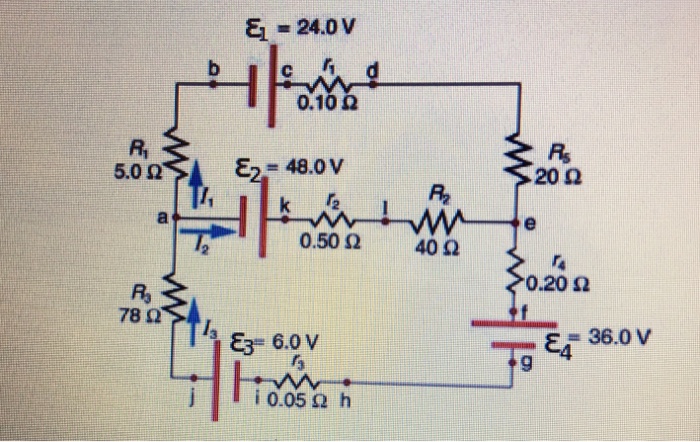
Transcribed image text: Consider the circuit diagram depicted in the figure. What equation do you get when you apply the loop rule to the loop abcdefgha?

Voltage Sensor A Circuit Diagram And B Final Circuit Design Download Scientific Diagram
Consider the circuit shown in Figure on page 8 6 0. (a) Find the voltage across the 3 . 0 0 − Ω resistor. (b) Find the current in the 3 . 0 0 − Ω resistor.
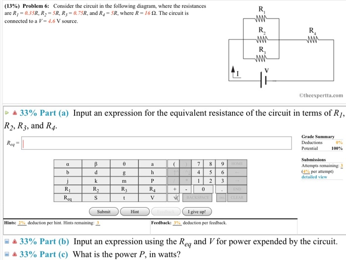
Solved 13 Problem 6 Consider The Circuit In The Chegg Com
Truth table of D Flip-Flop: The D (Data) is the input state for the D flip-flop. The Q and Q’ represents the output states of the flip-flop. According to the table, based on the inputs the output changes its state. But, the important thing to consider is all these can occur only in the presence of the clock signal.

Time Constant Calculations Worksheet Dc Electric Circuits
Consider the following circuit diagram. (a) Find the current flowing through the 5 Ω resistor. (b) Find the potential difference across the 3 Ω resistor. (c)...
Solved Consider The Circuit Depicted In The Diagram Chegg Com
Consider the circuit diagram below, bind I_x(t) for t greaterthanorequalto 0. This problem has been solved! See the answer ...
Gate Cse 2006 Question 37 Gate Overflow
An electric potential diagram is a conceptual tool for representing the electric potential difference between several points on an electric circuit. Consider the circuit diagram below and its corresponding electric potential diagram. The circuit shown in the diagram above is powered by a 12-volt energy source.
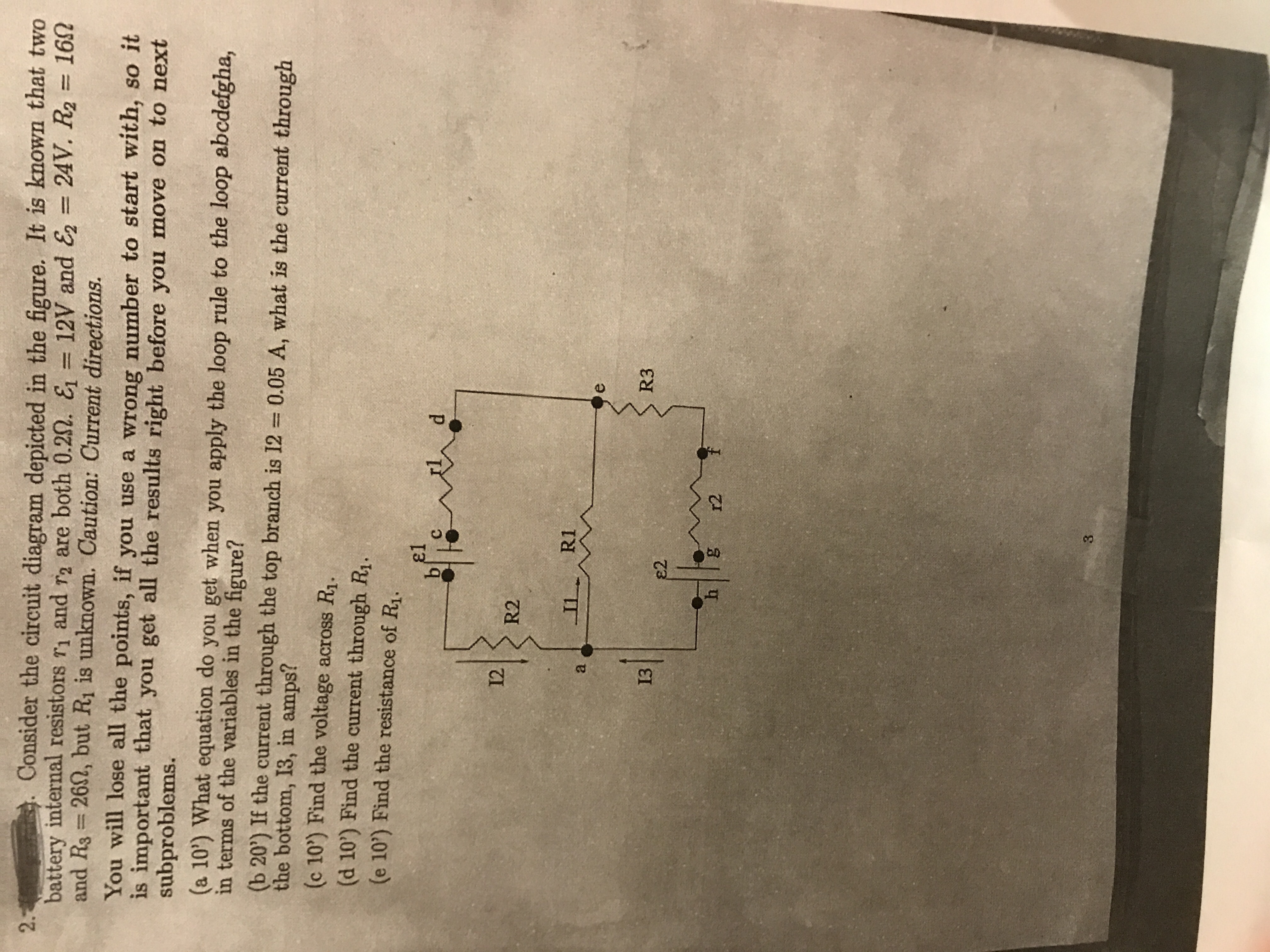
Answered Consider The Circuit Diagram Depicted Bartleby
Consider the following circuit diagram: 20 kΩ 3 V 2 V 15 V 20 ΚΩ 40 k2 R 160 k2 -15 V What is the resistance R value to obtain output voltage v, equals to - 5.625 V ? (a) 20 kN (b) 80 kN (c) 160 kN (d) does not exist
Gate Cse 2006 Question 37 Gate Overflow
Consider the combination circuit in the diagram at the right. Use the diagram to answer the following questions. (Assume that the voltage drops in the wires themselves in negligibly small.)
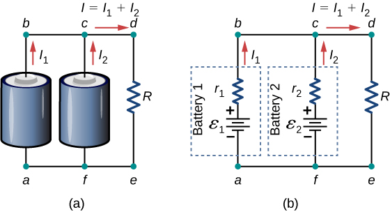
Kirchhoff S Rules University Physics Volume 2

Berapa Arus Yang Mengalir Disetiap Resistor Pada Gambar Rangkaian Dibawah Ini Brainly Co Id

Circuit Diagram Of The Home Made Overdrive Effect Pedal Download Scientific Diagram
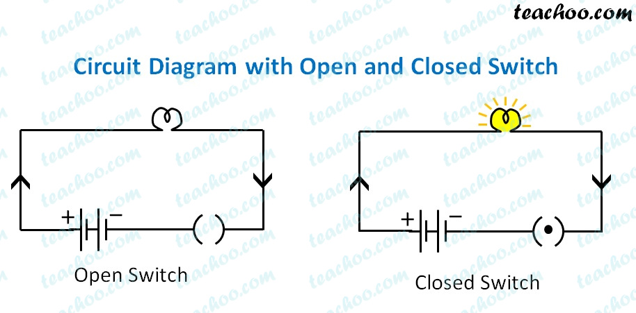
Electric Circuit Diagram Symbol Open And Closed Circuit Teachoo

Consider The Circuit In The Diagramcalculate I Total Resistance Of Circuitii Potential Different Brainly In
Jual Circuit Diagram Data Skema Elektronik Ir 5570 6570 Di Lapak Ark Store Bukalapak

Hartley Oscillator And Hartley Oscillator Theory
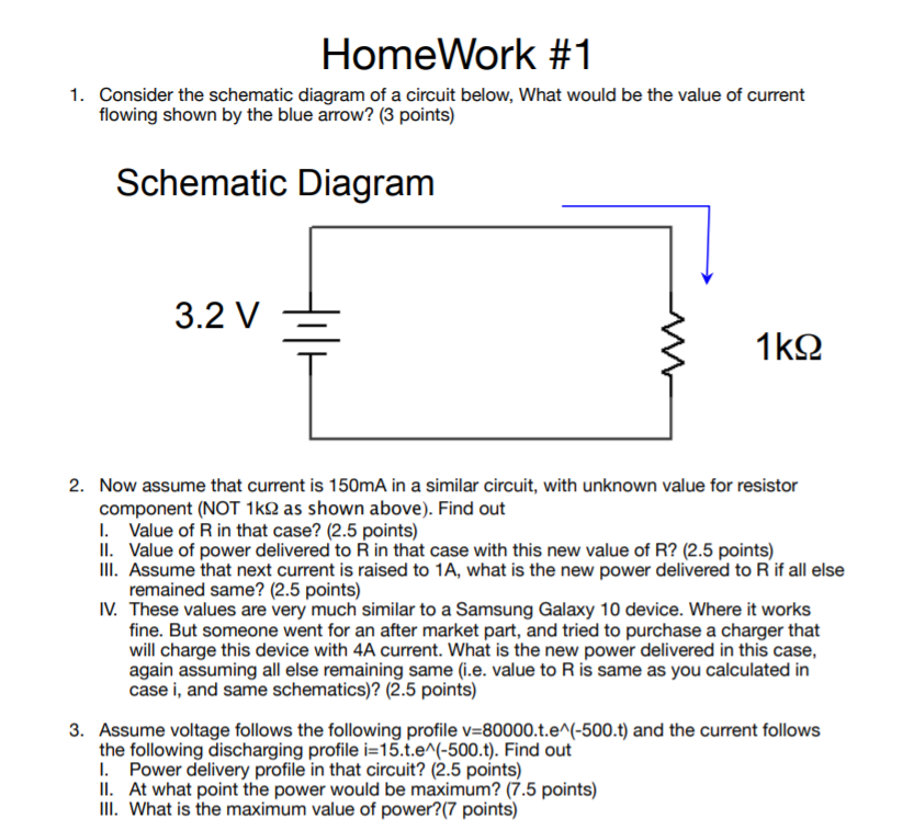
Solved Homework 1 1 Consider The Schematic Diagram Of A Chegg Com
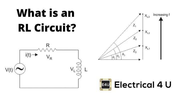
Rl Series Circuit Analysis Phasor Diagram Examples Derivation Electrical4u
Consider The Circuit Switched Network In Figure 1 13 Recall That There Are 4 Circuits On Each Link Label The Four Switches A B C And D Going In The Clockwise Direction Cpen
0 Response to "40 consider the circuit in the diagram"
Post a Comment