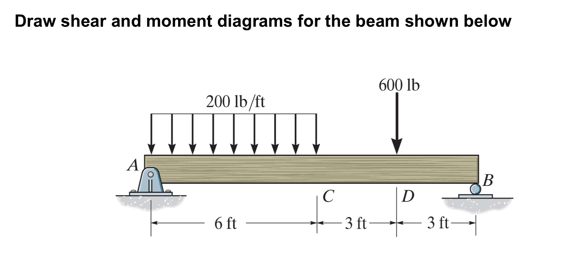
40 draw the shear diagram for the beam. set p = 600 lb, a = 5 ft, b = 7 ft.
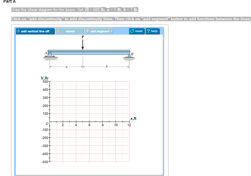
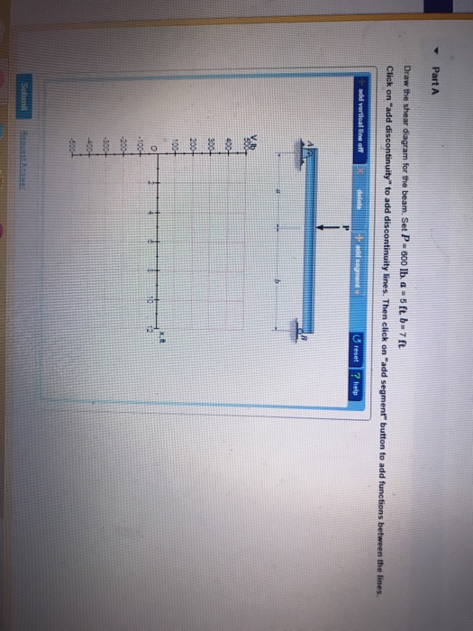
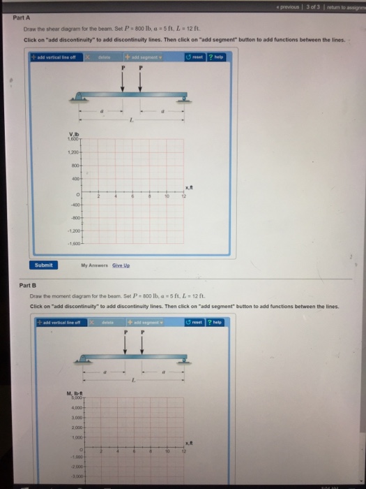
Transcribed image text: Problem 7.47 Part A Draw the shear diagram for the beam Set P 600 lb, a 5 ft, b ft Click on "add discontinuity" to add discontinuity ... Mechanical Engineering questions and answers. Draw the shear diagram for the beam. Set P = 800 lb, a = 5 ft. L = 12 ft. Click on "add discontinuity" to add discontinuity lines. Then click on "add segment" button to add functions between the lines. Draw the moment diagram for the beam.
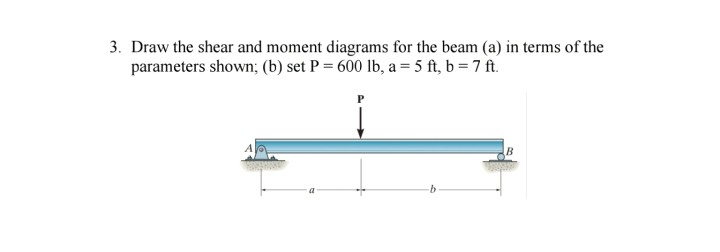
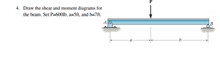
Question: draw the shear and moment diagram for the beam (a) in terms of the parameters shown; (b) set P= 600lb, a=5ft, b=7ft ...
Draw the shear diagram for the beam. set p = 600 lb, a = 5 ft, b = 7 ft.
Positive bending moment diagram drawn BELOW the beam SHEAR FORCE & BENDING ... Then, draw the shear force diagram (SFD) and bending moment diagram (BMD). b) If P = 20 kN and L = 6 m, draw the SFD and BMD for the beam. P kN L/2 L/2 A B EXAMPLE 4 . P kN L/2 L/2 R ... then draw the shear force diagram (SFD) and bending moment diagram (BMD). 5 kN/m ... Answer to: Draw the shear and moment diagrams for the beam (a) in terms of parameters shown; (b) set P = 600 lb, a = 5 ft, b = 7 ft By signing up,... Transcribed image text: Part A Draw the shear diagram for the beam. Set P = 600 lb, a = 5 ft, b = 7 ft. Click on "add discontinuity" to add discontinuity lines. Then click on "add segment" button to add functions between the lines. + + O @ b No elements selected V, lb 500 400 300 200 100 2, ft 0+ 0 -100- 2 4 6 8 10 12 -200 -300 -400 -500 Part B Draw the moment diagram for the beam.
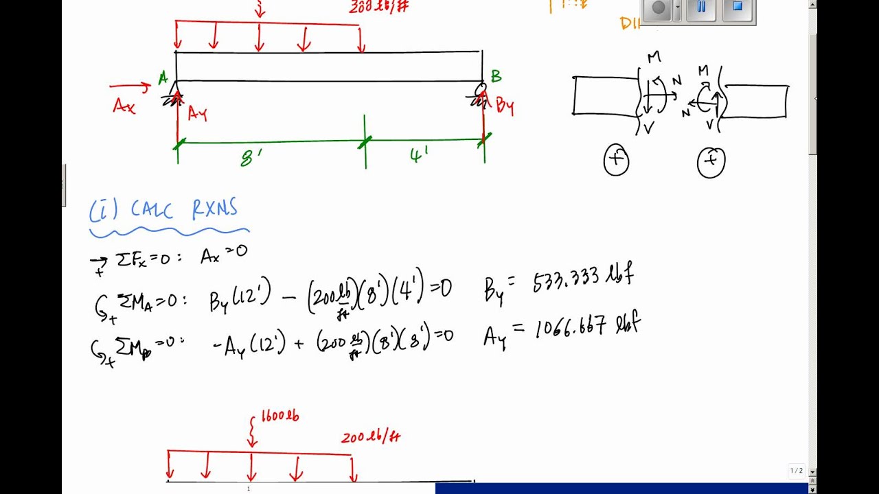
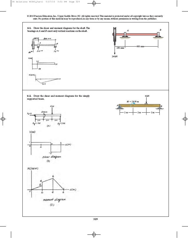
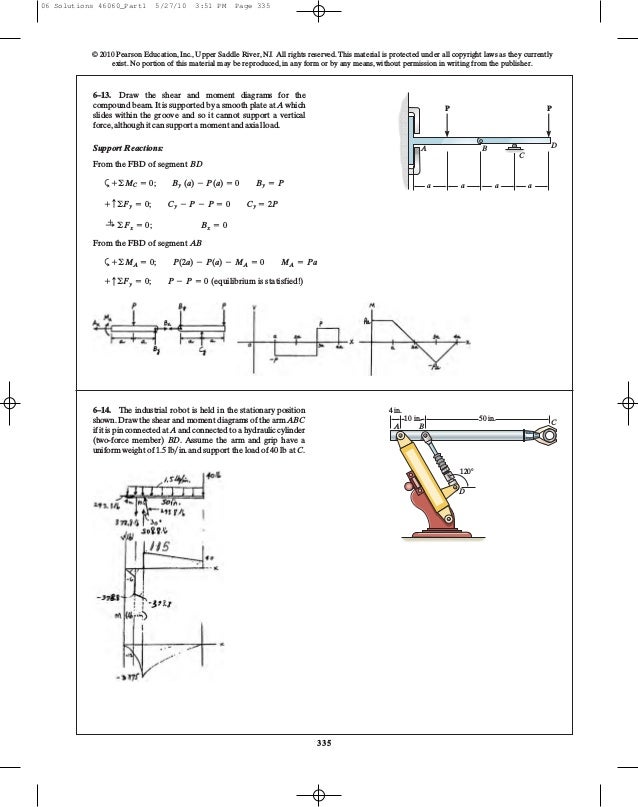
Draw the shear diagram for the beam. set p = 600 lb, a = 5 ft, b = 7 ft.. add vertical line off U reset help 400 12 100 Submit My Answers give up Part B Draw the moment diagram for the beam. Set P* 600 lb, a 5 ft, b 7 ft. This problem ... For this problem establish the x axis with the origin at the left side of the beam and obtain the internal shear and moment as a function of x. Use the results to plot the shear and moment diagrams. Draw the shear and moment diagrams for the beam (a) in terms of the parameters shown; (b) set p = 600lb, a = 5ft, b=7ft . Answers and Replies Feb ... A and smooth journal bearing at B. Draw the shear and moment diagrams for the shaft. A B 1 m 1 m 1 m 900 N 400 N m M (N m) x (m) x (m) ... overhanging beam. 3 ft 3 ft 200 lb/ft 400 lb 6 ft 400 lb A B M (lb ft) x (ft) V (lb) 0 400 0 12 x (ft) 600 1200 1200 300 600 400 3 6 369 12 9 Ans: Hibbeler_Chapter 6_Part 1 (487-517).qxd 2/12/13 11:07 AM ... Set P = 600 lb, a = 5 ft, b = 7 ft. Click on "add discontinuity" to add discontinuity lines. Then click on "add segment" button to add functions between the ...
Set P = 600 lb. a = 5 ft. b = 7 ft Click on add discontinuity to add discontinuity lines. Then click on add segment button to add functions between the lines ... Transcribed image text: HW 15 Problem 7.47 Part A Draw the shear diagram for the beam. Set P- 600 lb, a 5 ft, b 7ft Click on "add discontinuity" to add ... Set P = 600 lb, a = 5 ft, and b = 7 ft. This problem has been solved! See the answer ... Draw the shear and moment diagrams for the beam. (a) in terms of the parameters shown; (b) set P = 600 lb, a = 5 ft, B = 7 ft. fullscreen Expand. Transcribed Image Text.
Draw the shear and moment diagrams for the beam (a) in terms of the parameters shown; (b) set P = 600 lb, a = 5 ft, b = 7 ft. 2 | P a g e 2. Draw the shear and moment diagrams for the cantilevered beam. Shear and moment diagrams and formulas are excerpted from the Western Woods Use ... L = span length of the bending member, ft. R = span length of the bending member, in. M = maximum bending moment, in.-lbs. P = total concentrated load, lbs. R = reaction load at bearing ... 7-48 A R 1 Shear a b Figure 25 Beam Fixed at Both Ends–Concentrated ... Transcribed image text: Draw the shear diagram for the beam. Set P - 600 lb, a = 5 ft, b -7 ft. Click on "add discontinuity" to add discontinuity lines. Set P600 Ib, a 5 ft, b 7 ft. Click on "add discontinulty" to add discontinulty lines. Then click on "add segment" button to add functions between the Ilines. +0 ...
2
A concentrated load, such as P in Fig. 4.1(a). In contrast a distributed load is applied over a finite area. If the distributed load acts on a very narrow area, the load may be approximated by a line load. The intensity w of this loading is expressed as force per unit length (lb/ft, N/m, etc.)
2
Transcribed image text: Part A Draw the shear diagram for the beam. Set P = 600 lb, a = 5 ft, b = 7 ft. Click on "add discontinuity" to add discontinuity lines. Then click on "add segment" button to add functions between the lines. + + O @ b No elements selected V, lb 500 400 300 200 100 2, ft 0+ 0 -100- 2 4 6 8 10 12 -200 -300 -400 -500 Part B Draw the moment diagram for the beam.

Find The Distribution Asfunctions Of Xl Of The Noripal N And Shear Wi Forces And Moment M For The Beam Shown In The Figure X I Pdf Free Download
Answer to: Draw the shear and moment diagrams for the beam (a) in terms of parameters shown; (b) set P = 600 lb, a = 5 ft, b = 7 ft By signing up,...
Solved 3 Draw The Shear And Moment Diagrams For The Beam Chegg Com
Positive bending moment diagram drawn BELOW the beam SHEAR FORCE & BENDING ... Then, draw the shear force diagram (SFD) and bending moment diagram (BMD). b) If P = 20 kN and L = 6 m, draw the SFD and BMD for the beam. P kN L/2 L/2 A B EXAMPLE 4 . P kN L/2 L/2 R ... then draw the shear force diagram (SFD) and bending moment diagram (BMD). 5 kN/m ...

Statics 7 82 Draw The Shear And Moment Diagrams For The Beam Youtube
2

Drawing Shear And Moment Diagrams For Beam Youtube
2

I 50 Lb Ft 200 Lb Ft B Os 6 For The Beam Shown Draw The Shear And Moment Homeworklib

329 6 1 Draw The Shear And Moment Diagrams For Aerostudents
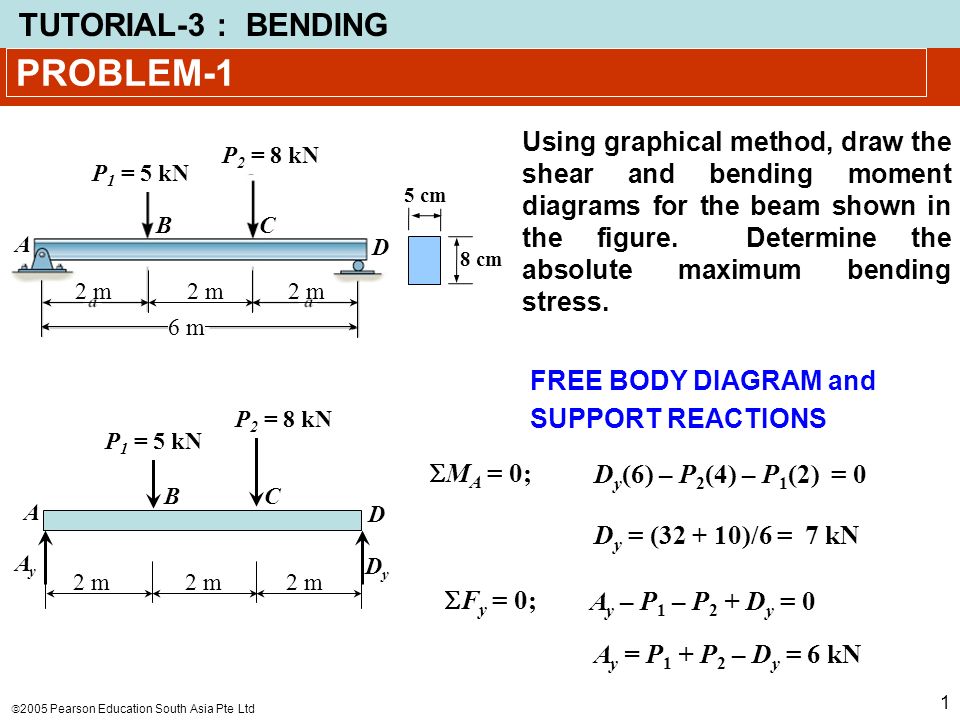
Problem 1 Using Graphical Method Draw The Shear And Bending Moment Diagrams For The Beam Shown In The Figure Determine The Absolute Maximum Bending Ppt Video Online Download
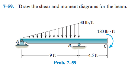
Solved 7 59 Draw The Shear And Moment Diagrams For The Beam Chegg Com
Structural Analysis By R C Hibbeler 8th Edition
Solved Draw The Shear And Moment Diagrams For The Beam A In Terms Of The Parameters Shown B Set P 600 Mathrm Lb A 5 Mathrm Ft B 7 Mathrm Ft
Solved Draw The Moment Diagram For The Beam Set P 600 Lb Chegg Com
Chapter 7
2

1 6 Arches And Cables Engineering Libretexts

Draw The Shear And Moment Diagrams For The Beam A In Terms Of Parameters Shown B Set P 600 Lb A 5 Ft B 7 Ft Study Com

Answer Correct Part E Determine The Moment As A Function Of Where Express Your Course Hero
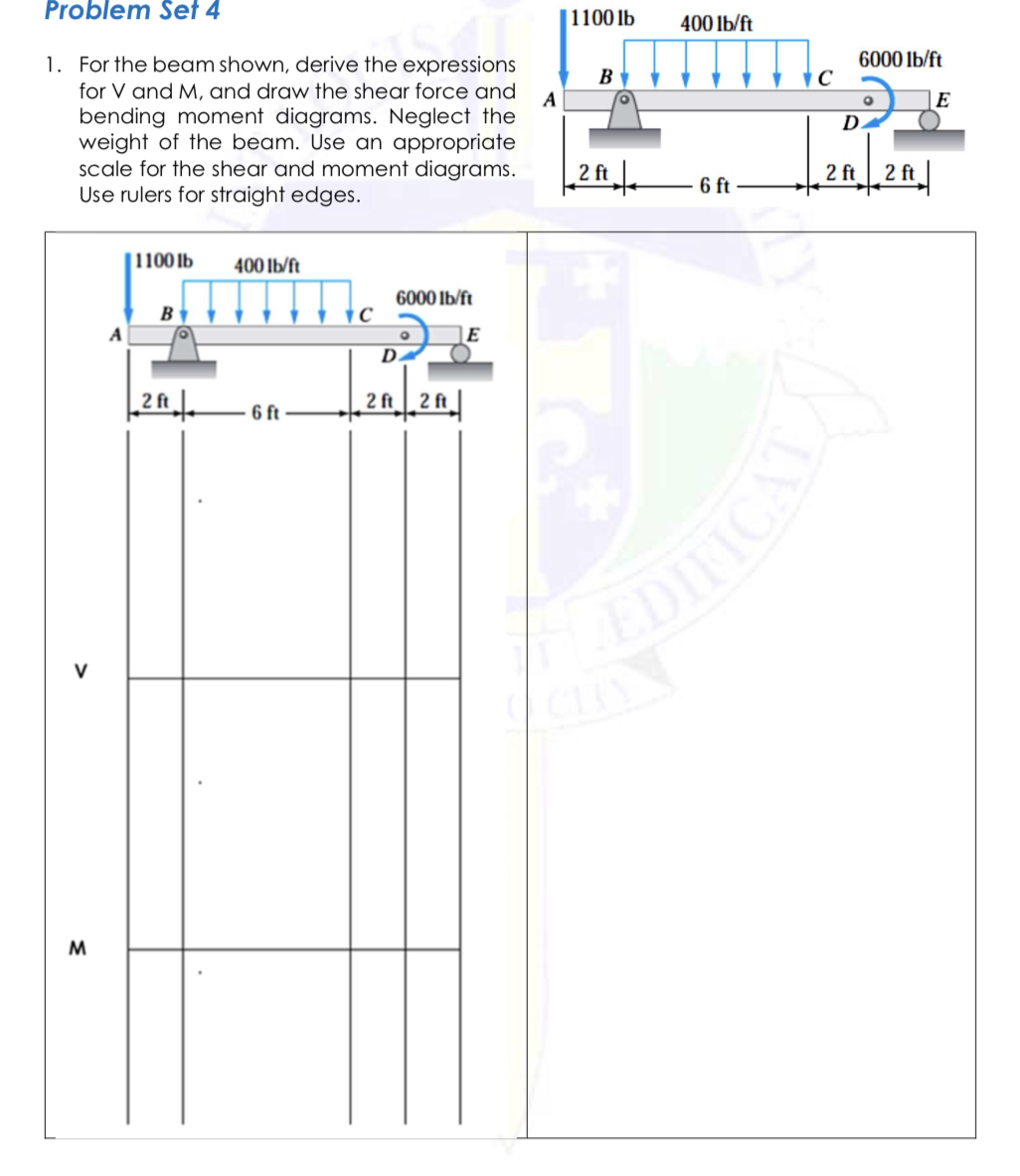
Answered Problem Set 4 1100 Lb 400 Lb Ft 6000 Bartleby
2
Solved Draw Shear And Moment Diagrams For The Beam Shown Chegg Com
Solved Draw The Shear Diagram For The Beam Set P 600 Ib A Chegg Com
Drawing Shear And Moment Diagrams Example Mechanics Of Materials And Statics Youtube

Draw The Shear And Moment Diagrams Then Answer The Question The Distance X Is Measured From Points A To The Right Question At X 1 1 Ft V Ib M
Bvhkqeaayvbnsm
2
2
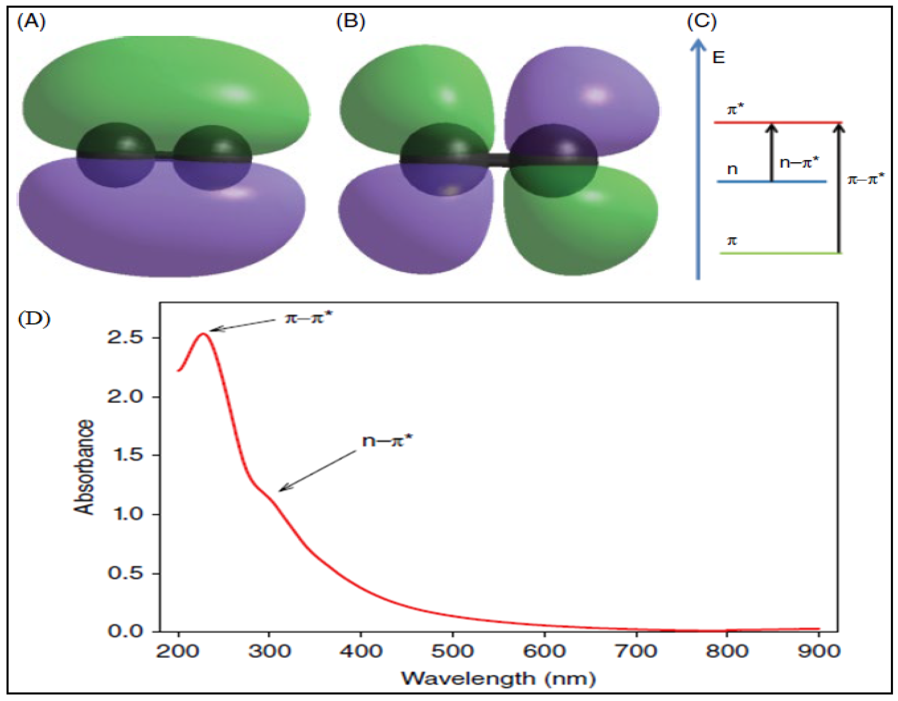
Chemengineering Free Full Text Graphene Oxide Synthesis Properties And Characterization Techniques A Comprehensive Review Html
2

Draw The Shear Diagram For The Beam Set P 800 Lb A 5 Ft L 12 Ft Wiring Site Resource
Solved Draw The Shear And Moment Diagrams For The Beam Set Chegg Com
Ch06 07 Pure Bending Amp Transverse Shear

Draw The Shear And Moment Diagrams For The Beam A In Terms Of The Parameters Shown B Set P 600 Lb A 5 Ft B 7 Ft Course Hero
Ch06 07 Pure Bending Amp Transverse Shear

Mekanika Teknik
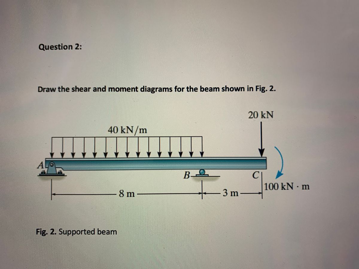
Answered Question 2 Draw The Shear And Moment Bartleby
2
Solved Draw The Shear Diagram For The Beam Set P 800 Lb Chegg Com
0 Response to "40 draw the shear diagram for the beam. set p = 600 lb, a = 5 ft, b = 7 ft."
Post a Comment