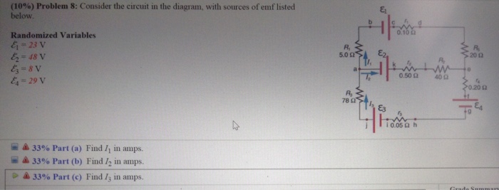
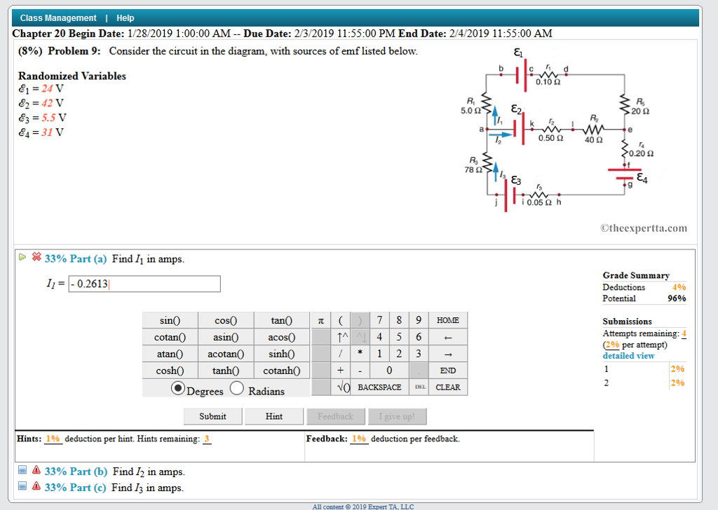
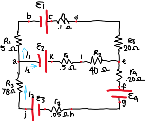
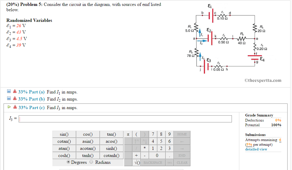
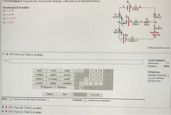
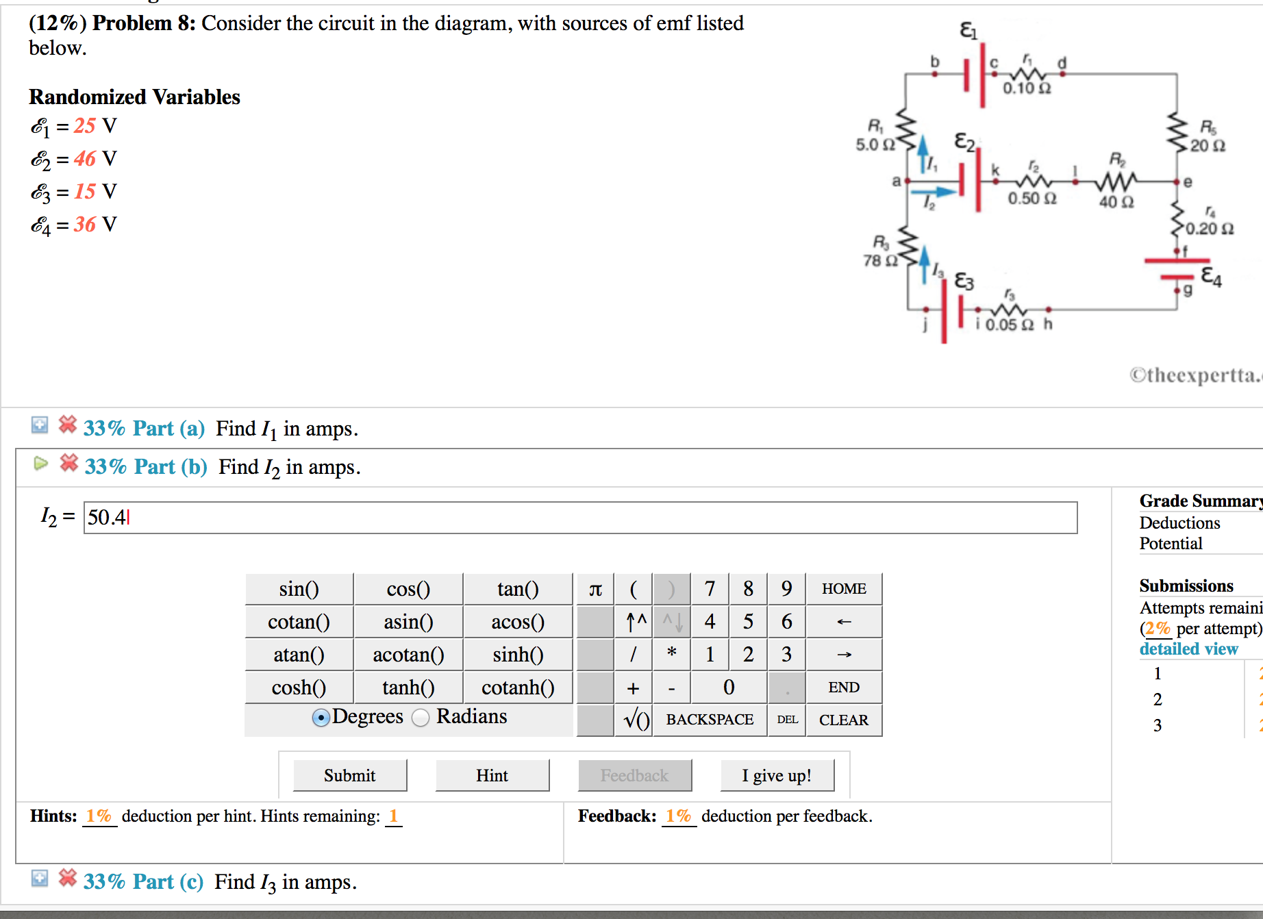
34 consider the circuit in the diagram, with sources of emf listed below.
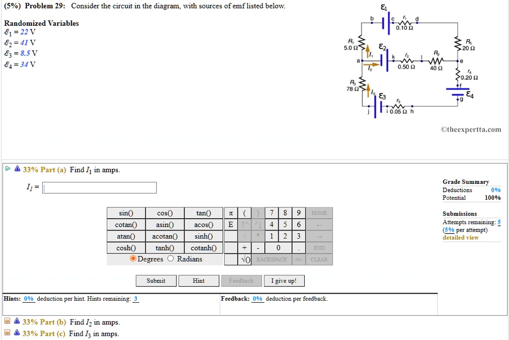
Answer to: Consider the circuit in the diagram, with sources of emf listed below. Randomized Variables \varepsilon_1 = 29 V, \varepsilon_2 = 41 V,...
The headlamp and two IDENTICAL tail lamps of a scooter are connected in parallel to a battery with unknown internal resistance as shown in the simplified circuit diagram below. The headlamp has a resistance of \(\text{2,4}\) \(\text{Ω}\) and is controlled by switch \(\textbf{S}_1\).
This photo about: Consider the Circuit In the Diagram with sources Of Emf Listed Below, entitled as Electrical Engineering Archive November 01 2014 Consider The Circuit In The Diagram With Sources Of Emf Listed Below - also describes Electrical Engineering Archive November 01 2014 and labeled as: ], with resolution 1958px x 1457px

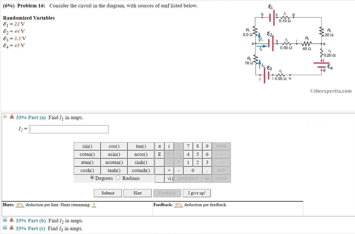
Consider the circuit in the diagram, with sources of emf listed below.
design a circuit so that the device will operate properly when the circuit is connected across a battery of emf 24 volts and negligible internal resistance. Within the dashed-line box in the diagram to the right, draw the circuit using the symbol for the device and the appropriate symbol for each 3-ohm resistor.
2. The source that maintains the constant currentin a closed circuit is called a source of "emf." a) One can think of such a source as a "charge pump" =⇒ forces electronstomove in adirection oppositetheE-field, hence current, inside a source. b) The emf, E, of a source is the work done per unit charge =⇒ measured in volts. c) A ...
(b) The circuit diagram of the two batteries and the load resistor, with each battery modeled as an idealized emf source and an internal resistance. When voltage sources are in series, their internal resistances can be added together and their emfs can be …
Consider the circuit in the diagram, with sources of emf listed below..
An electric circuit is a path through which charges can flow. A schematic diagram for a circuit is sometimes called a circuit diagram. Any element or group of elements in a circuit that dissipates energy is called a load. A simple circuit consists of a source of potential difference
Consider the circuit in the diagram, with sources of emf listed below. Randomized Variables ℰ 1 = 26 V ℰ 2 = 44 V ℰ 3 = 14.5 V ℰ 4 = 39 V. Part (a) Find I 1 in amps. Part (b) Find I 2 in amps. Part (c) Find I 3 in amps.
Answer to consider the circuit in the diagram with sources of emf listed below. For teachers for schools for working scholars log in. Three Phase Electric Power Explained Engineering Com Consider the circuit in the diagram with sources of emf listed below randomized variables 6 24 v 01052 50 ω 20ω 3. Consider the circuit in the diagram with sources of emf listed. This problem has been solved ...
The label on a battery-powered radio recommends the use of a rechargeable nickel-cadmium cell (nicads), although it has a 1.25-V emf, whereas an alkaline cell has a 1.58-V emf. The radio has a 3.20 Ω 3.20 Ω resistance. (a) Draw a circuit diagram of the radio and its battery.
Problem: Consider the circuit in the diagram, with sources of emf listed below.Randomized Variablesℰ1 = 21 Vℰ2 = 49 Vℰ3 = 9.5 Vℰ4 = 39 Va) Find I1 in amps.B) Find I2 in amps.C) Find I3 in amps.
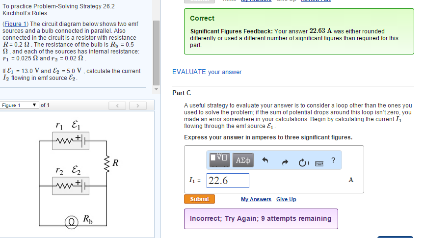
The circuit diagram below shows two emf sources and a bulb connected in parallel. Also connected in the circuit is a resistor with resistance R = 0.2 . The resistance of the bulb is Rb = 0.5 , and each of the sources has internal resistance: r1 = 0.025? and r2 = 0.02 ? .
17.2.2019 · 20. Draw a circuit diagram for use of n-p-n transistor as an amplifier in common emitter configuration. The input resistance of a transistor is 1000 . On changing its base current by , the collector current increases by 2 mA. If a load resistance of 5k is used in the circuit, calculate: (i) the current gain,(ii) voltage gain of the amplifier. 21.
(7%) Problem 3: Consider the circuit in the diagram, with sources of emf listed below, ca 0.10 0 Randomized Variables E = 22 V 5.0 20 0 EL = 42 V [T, KyHe 1 0.50 40 a . E3 = 6.5 V a E4 = 38 v 0.20 0 78 a ji 05 a h Otheexpertta.com A 33% Part (a) Find I1 in amps. a 33% Part (b) Find 12 in amps.
Faraday's law of induction (briefly, Faraday's law) is a basic law of electromagnetism predicting how a magnetic field will interact with an electric circuit to produce an electromotive force (EMF)—a phenomenon known as electromagnetic induction.It is the fundamental operating principle of transformers, inductors, and many types of electrical motors, generators and …
Electrical Engineering Handbook. Enter the email address you signed up with and we'll email you a reset link.
Problem 6: Consider the circuit in the diagram, with sources of emf listed below Randomized Variables EI-25 V & 49 V 0.102 5.0 Ω 20Ω R2 0.50 Ω 40Ω 4 31 V 0.20 Ω Ra 9 ¡0.05 Ω h Otheexpertta.com Part (a) Find /1 in amps. . tan( cos(0) cotan0asin) acos(0 sin() 4 5 6 *1 23 0 atan()acotan( sinh() cosh)tanh) cotanh O Degrees O Radians BACKSPACE CLEA Submit Hint I give up!
Consider the battery in the figure. The voltage of the battery is defined as the difference in electric potential between its positive and negative terminals: i.e., the points and , respectively.As we move from to , the electric potential increases by volts as we cross the emf, but then decreases by volts as we cross the internal resistor. The voltage drop across the resistor follows from Ohm ...
Answer to: Consider the circuit in the diagram with in the diagram with sources of emf listed below Randomized variable E 1 = 25 v E 2 = 46v ...
Consider the Circuit In the Diagram with sources Of Emf Listed Below. training ueeneee104a solve problems in d c australian government department of education and training training gov au magnetic shielding materials emf safety superstore circuit breaker shield decorative magnetic shielding a circuit breaker box or fuse box in the bedroom living room kitchen or other living space can
Pharmacological Basis For Nursing Interventions II (NUR 3192) Computer Information Systems (CIS 401) Human Anatomy (ANP 300) Introduction to Organic and Biological Chemistry (CHEM120-62398)
Consider the circuit in the diagram with sources of emf listed below. A 303 v emf is connected to the terminals a and b as shown above. Consider the circuit in the diagram with sources of emf listed below. Also connected in the circuit is a resistor with resistance r 02 ohms.
F problem consider the circuit in the diagram with sources of emf listed below randomized variables 81 22 v 82 41v 83 95 v 84 25 v 010 50 20 050 40 020n 005 othcexperttacom 33 fart a find in 13672
Consider the circuit in the diagram with sources of emf listed below. Consider the circuit in the diagram with sources of emf listed below. Show more 1 consider the circuit in the diagram below in which r 10 ω. With resolution 1584px x 1379px. Ohm S Law Electric Circuits Siyavula Solved 10 Problem 11 Consider The Circuit In The Diag
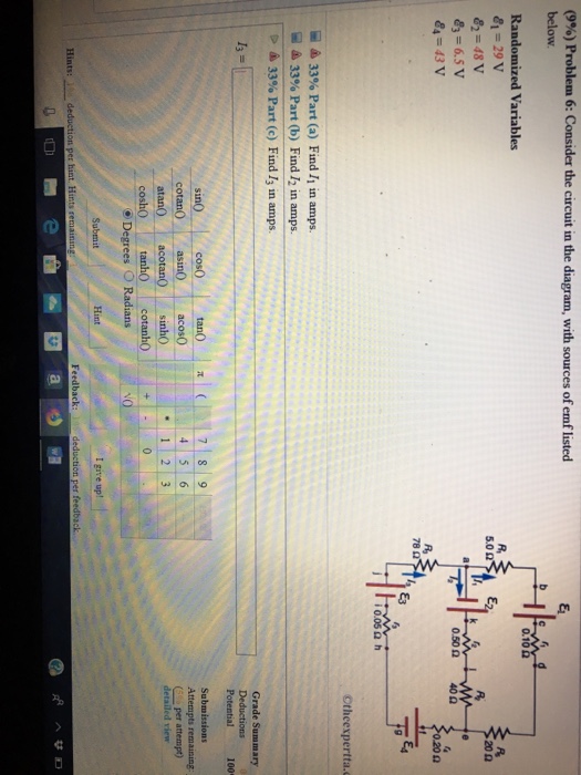
Transcribed image text: (9%) Problem 6: Consider the circuit in the diagram, with sources of emf listed below Randomized Variables 81-29 V 0.1 R, 20Ω 83-6.5 V 84-43 V 0.50 Ω 40Ω 020 Ω 78 Ctheexpertta.c Li 33% Part (a) Find 11 in amps. 33% Part (b) Find 12 in amps. 33% Part (c) Find 13 in amps. Grade Summary Deductions Potential100 Submissions acos atan0 acotan sinh0 (Gso per attempt ...
We first consider the RL circuit of (b). Once is closed and is open, the source of emf produces a current in the circuit. If there were no self-inductance in the circuit, the current would rise immediately to a steady value of However, from Faraday's law, the increasing current produces an emf across the inductor. In accordance with Lenz's law, the induced emf counteracts the increase in ...
Questions 14-15 refer to the following diagram that shows part of a closed electrical circuit. 14. The electrical resistance of the part of the circuit shown between point X and point Y is (A) 4/3 (B ) 2 (C) 4 (D) 6 15. When there is a steady current in the circuit, the amount of charge passing a point per unit of time is
RLC Circuit Questions and Answers. Get help with your RLC circuit homework. Access the answers to hundreds of RLC circuit questions that are explained in a …
Unit 7: Electric Circuits Multiple Choice Portion 1. The diagram below shows part of an electrical circuit. What are the magnitude and direction of the current passing through resistor R 5 ? a. 6.0 A towards the left b. 12.0 A towards the left c. 2.0 A towards the right d. 8.0 A towards the right 2. A 12 V battery is connected to a 60 Ω ...
Consider the circuit shown in Figure P28.9. Find ... In (c), the source of emf is traversed in the direction of the emf (from - to +), and the ... Draw the circuit diagram and assign labels and symbols to all known and unknown quantities. Assign directions to the currents.
Electric Power Questions and Answers. Get help with your Electric power homework. Access the answers to hundreds of Electric power questions that …
Consider a simple circuit consisting of a battery as the emf source and a resistor of resistance R, as shown in Figure 7.2.1. Figure 7.2.1 A simple circuit consisting of a battery and a resistor Assuming that the battery has no internal resistance, the potential difference (or
Click here👆to get an answer to your question ️ (10%) Problem 10: Consider the circuit in the diagram, with sources of emf listed below. 5.023 > E2. Randomized Variables & = 28 V E2 = 43 V Ez = 11 V E = 41 V 02 me 400 78 22 TEA W 10.050 h
If you are handy, you can use the magnetic shielding materials listed below to make your own hinged shield. If you want an easier solution, here it is. It's a picture (or poster) in a nice frame, with high performance Giron shielding material behind the picture. Just put a nail above the breaker box and hang the shielded picture where you need it.
Consider the circuit in the diagram, with sources of emf listed below. Randomized Variables E = 22 V Ez = 44 V 0.102 Ez = 3.5 V R 5.0 2 E2, R 202 E4 = 45 V R a e 0.50 2 40 2 14 0.20 요 R, 78 2 E3 E4 g i 0.05 2 h A. Find I in amps. B. Find I2 in amps. C. Find I3 in amps. ww. Consider the circuit in the diagram, with sources of emf listed below.
Consider the circuit in the diagram with sources of emf listed below. A 303 v emf is connected to the terminals a and b as shown above. Training ueeneee104a solve problems in d c australian government department of education and training training gov au magnetic shielding materials emf safety superstore circuit breaker shield decorative magnetic shielding a circuit breaker box or fuse box in ...
12.3.2020 · A boost converter (step-up converter) is a DC-to-DC power converter that steps up voltage (while stepping down current) from its input (supply) to its output (load).It is a class of switched-mode power supply (SMPS) containing at least two semiconductors (a diode and a transistor) and at least one energy storage element: a capacitor, inductor, or the two in …
One of the simplest ways to make a battery powered High Voltage power supply is to use a common car ignition coil. Ignition coils are a type of induction transformer based on the Tesla Coil invented by Nikola Tesla in 1891. The voltage rise is not given by the turns ratio like in a standard transformer, but is proportional to the rate of change of current in the primary circuit.
Consider The Circuit In The Diagram With Sources Of Emf Listed. Collected from the entire web and summarized to include only the most important parts of it. Can be used as content for research and analysis.
Consider the circuit in the diagram, with sources of emf listed below. Randomized Variables epsilon _1 = 26 V epsilon _2 = 46 V epsilon _3 = 12.5 V epsilon _4 = 42 V Find I_1 in amps. Find I_2 in amps.
Robert L Boylestad - Introductory Circuit Analysis, Tenth Edition. T. Person. Download Download PDF. Full PDF Package Download Full PDF Package. This Paper. A short summary of this paper. 10 Full PDFs related to this paper. Read Paper. Download Download PDF.
5-a) An RL circuit is driven by an AC voltage source as shown in the figure. (Figure 1). On the phasor diagram below, adjust the phasor that represents the voltage across the resistor (VRVRV_R) at the instant indicated to the proper orientation.
(b) The circuit diagram of the two batteries and the load resistor, with each battery modeled as an idealized emf source and an internal resistance. When voltage sources are in series, their internal resistances can be added together and their emfs can be added together to get the total values.

16 problem 4 consider the circuit in the diagram with sources of emf listed below randomized variables 81 23 v 82 49 v 83 95v 8436 v 010 20 n 40 q 020 4 veras acosta mauro mauro veras_acosta 62108
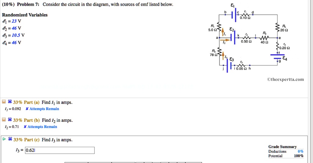
109 problem 7 consider the circuit in the diagram with sources of emf listed below randomized variables 8j 23v 62 46 v 6105v 64 46v od 20 40 4 020 n otheexpertta com 8339 part a find i in am 90654












0 Response to "34 consider the circuit in the diagram, with sources of emf listed below."
Post a Comment