39 water temp gauge wiring diagram
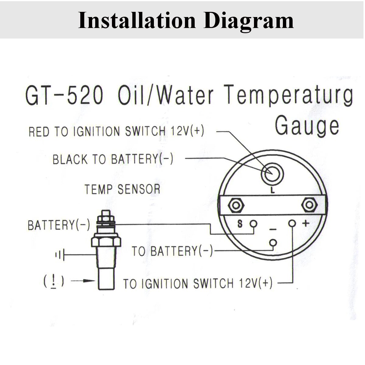
Autometer Water Temp Gauge Wiring - Wiring Diagrams Free As a safety precaution, the 12V wire attached to the positive I () terminal of the gauge should be fused before. Gauge, Water Temp, 2 1/16", °F, Electric, Ultra-Lite. RANGE: °F; LIGHTING: Incandescent; INSTRUCTIONS: Download. Description. is beneficial to add a T-fitting to install your new gauge and to keep the warning light operational. Vdo Water Temp Gauge Wiring Diagram - schematron.org Oct 15, 2018 · I. Installing the VDO Universal Temperature Sender Proper Wiring Between Gauge and Temperature Sender. 3. connected to the gauge (see Diagram B). 5. sender since the sender tip or bulb will not be immersed in the water flow. VDO Wiring Diagrams - Diagram will open in a new window.
Vdo Water Temp Gauge Wiring Diagram Diagram G Wiring Diagram WIRING OF POWER AND GROUND TO EACH GAUGE ILLUMINATION WIRING . °F/°C Water Temperature Gauge, Use with VDO Sender, 12V," Spade Connection Learn More ViewLine Ivory °F/°C Water Temperature Gauge 12/24V & . VDO Water Temp Gauge See more like this. VDO Cockpit Electrical Water Temperature Gauge 2 1/16" Dia Black Face ...

Water temp gauge wiring diagram
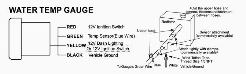
Vdo Water Temperature Gauge Wiring Diagram Feb 26, 2019 · Vdo water temperature gauge wiring diagram. I installed the vdo oil pressure and temperature gauges in my 1970 vw but will give you the concept on installing them in any vehicle. Coolant temperature oil temperature oil pressure fuel level and speed. All in one digital display system. This is part 1 on how to install vdo gauges. 1, 2, & 3 Wire Coolant Temperature Sensor Wiring Diagram In this powerful article, you will quickly learn the 1, 2, and 3 wire coolant temperature sensor wiring diagram. WATER TEMPERATURE - Installation Instructions Typical ... Wiring Diagram. Ignition harness / Fuse box. Red. Ignition 12V+. Green. Sensor input-. Ignition harness / Fuse box. Water temp sender output (red wire of ...
Water temp gauge wiring diagram. Autometer Water Temp Gauge Wiring Diagram MRC1 · MRC1 - Negative Coil Trigger Diagram · Nitrous Staging Diagram. is beneficial to add a T-fitting to install your new gauge and to keep the warning light operational. A. Water Temp: Install temperature sender (included). Instructions for: Temperature 2 1/16” Spek Pro Professional Racing Gauge . Temperature Gauge Wiring Diagram - Pinterest Temperature Gauge Wiring Diagram Electrical Switch Wiring, Light Switch Wiring, Electrical Circuit Diagram,. F. frans. 4 followers. More information. Smiths Water Temperature Gauge Wiring Diagram Sep 27, 2016 · Smiths water temperature gauge wiring diagram. 2500f1200c water temperature gauge use with vdo sender 12v 250 spade connection learn more cockpit international 1200c water temperature gauge use with vdo sender 24v 250 spade connection. Engine temperature directly affects combustion and moving internal parts. WATER TEMPERATURE - Installation Instructions Typical ... Wiring Diagram. Ignition harness / Fuse box. Red. Ignition 12V+. Green. Sensor input-. Ignition harness / Fuse box. Water temp sender output (red wire of ...
1, 2, & 3 Wire Coolant Temperature Sensor Wiring Diagram In this powerful article, you will quickly learn the 1, 2, and 3 wire coolant temperature sensor wiring diagram. Vdo Water Temperature Gauge Wiring Diagram Feb 26, 2019 · Vdo water temperature gauge wiring diagram. I installed the vdo oil pressure and temperature gauges in my 1970 vw but will give you the concept on installing them in any vehicle. Coolant temperature oil temperature oil pressure fuel level and speed. All in one digital display system. This is part 1 on how to install vdo gauges.
Water Temperature Gauge - Jaeger - 1750GTV
Installation Instructions Typical Layout

12/24V, 40° to 120°C Water Temp Gauge, 90° Sweep Dial [ALM ...
Help with Cluster Coolant Gauge Wiring | FD Owners Club - FDOC

ls motor in 86 Iroc coolant sensor/water temp - LS1TECH ...
Daily Planet Soarer
Seeking advice regarding how to trouble shoot a temperature ...
035919501 Coolant Temperature Sensor /water temperature ...
Does anyone have a picture of the water temp gauge sensor ...

Updating To An Electrical Gauge Package | Hotrod Hotline
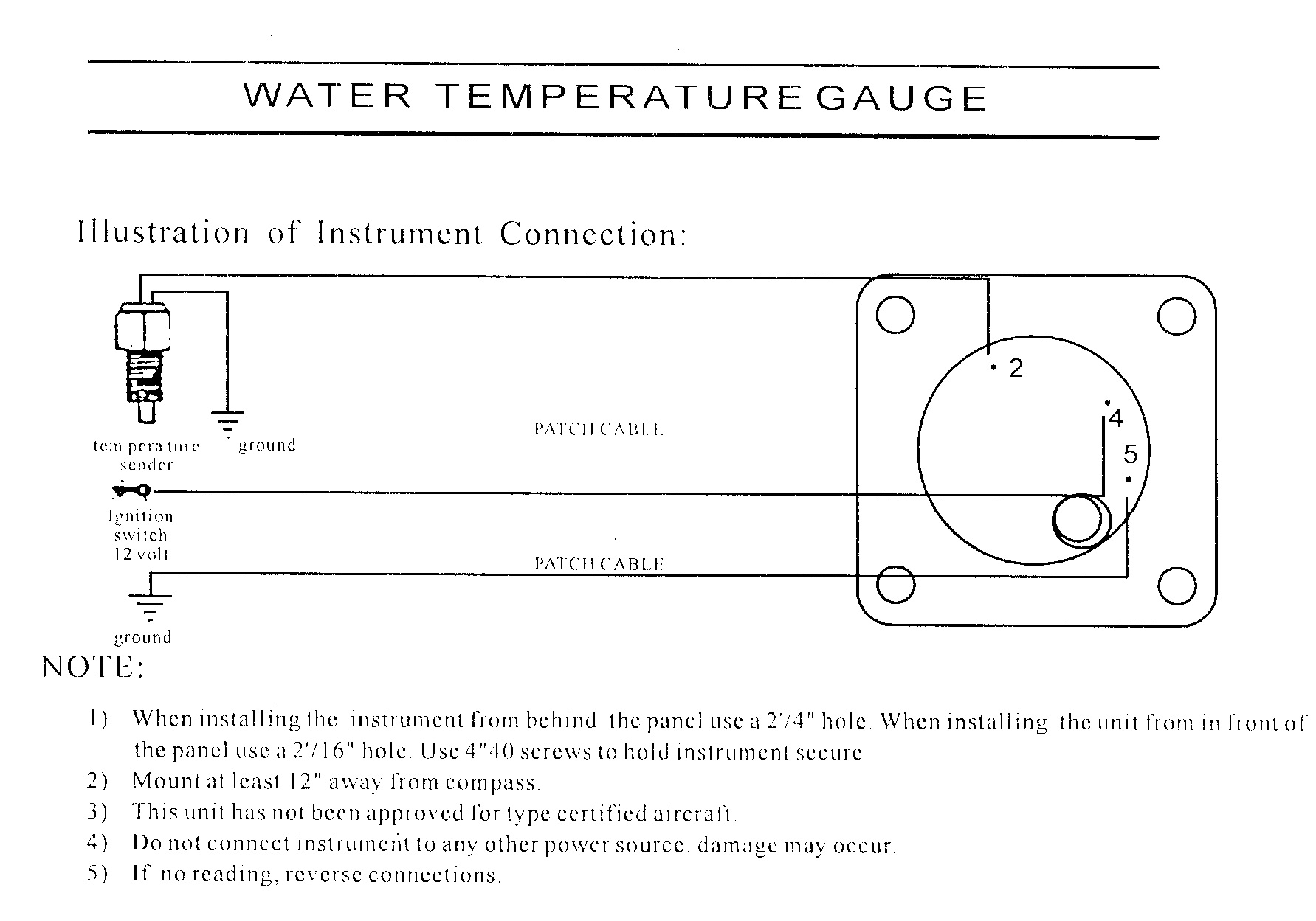
Swift Gauge 2-1/4 Water Temperature Gauge | Aircraft Spruce
VDO Temp Gauge Wiring | Defender Source Forum

Water Temperature Gauge Installation for Snowmobile

AEM 30-5140M Analog Oil Transmission Water Temperature Metric ...
Tech Shop
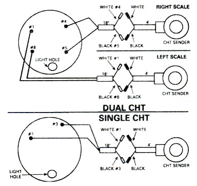
Cylinder head temperature gauge wiring diagram for Westach ...
VDO oil gauge hook up | Turbo Buick Forums
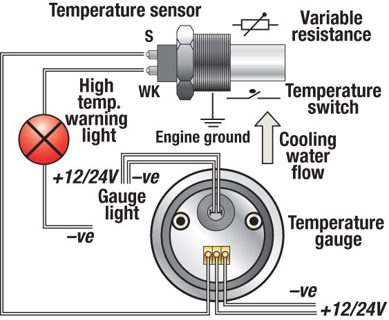
Troubleshooting Boat Gauges, Instruments and Meters | BoatUS

Car Black 2" 52mm Blue Digital LED Electronic Water Temp ...
2 Inch 52mm Digital Car Red LED Electronic Water Temp ...
42 Draft Designs
Water Temp Gauge
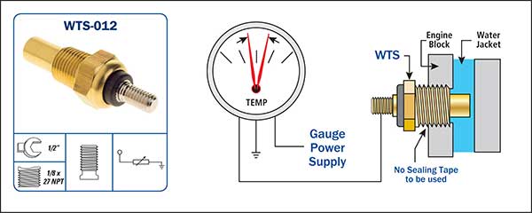
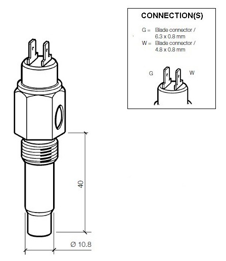
Water Temperature Sensors (WTS)
Autofab - 2" 52mm 7 Color Led Smoke Face Car Auto Water Temp ...
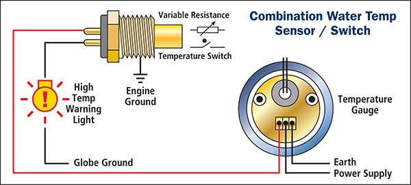
Water Temperature Sensors (WTS)
Vdo temp sensor gauge | YBW Forum

Water Temperature | By Type | Instruments, Displays and ...
Installation Instructions

Elite 10 Color Water Temperature Gauge
Electrical Diagrams
Installation Instructions

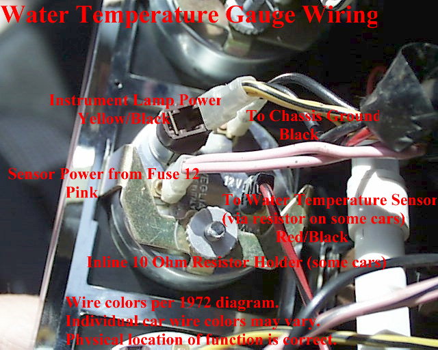
72-73 Temperature Gauge

Smiths Temp Gauge Wiring - Problems, Questions and Technical ...

DRAGON GAUGE LCD Water temperature gauge

Temperature Gauge Wiring Diagram | Electrical diagram, Gauges ...

Buy Mechanical Water Temperature Gauge Covers Aftermarket Car ...
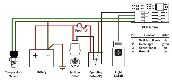
DIGIFIZmini
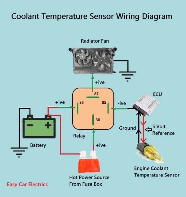
1, 2, & 3 Wire Coolant Temperature Sensor Wiring Diagram
Vdo Water Temperature Gauge 12v 38 120c/100 250f 24v Ler Dc ...
0 Response to "39 water temp gauge wiring diagram"
Post a Comment