36 shear moment diagram examples
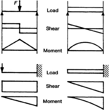
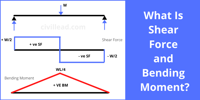
Mechanics eBook: Shear/Moment Diagrams Basic Example to Construct a Shear and Moment Diagram : Constructing shear and moment diagrams is similar to finding the shear and moment at a particular point on a beam structure. However, instead of using an exact location, the location is a variable distance 'x'. This allows the shear and moment to be a function of the distance, x. Shear force and bending moment diagram and examples ... Calculate the shear force and bending moment for the beam subjected to a concentrated load, then draw the shear force diagram (SFD) and bending moment diagram (BMD). Answer: By taking the moment at A, MA = 0 - RBy × 5 + 15 × 3 = 0 RBy = 9 kN Fy = 0 RAy + RBy = 15 RAy = 15 - 9 RAy = 6 kN Fx = 0 , RAx = 0 Shear force and bending moment diagram
PDF CIVL 3121 Shear Force and Bending Moment Diagrams for ... Example: Draw the shear and moment diagrams for the following beam using superposition: + = + CIVL 3121 Shear Force and Bending Moment Diagrams for Frames 4/5. Shear and Moment Diagrams by Superposition Example: Draw the shear and moment diagrams for the following beam using superposition. 10 ft. A 4 k/ft.
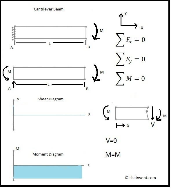
Shear moment diagram examples
PDF 4. Bending Moment and Shear Force Diagram S.F and B.M diagram (iv) Let us take an example: Consider a cantilever bean of 5 m length. It carries a uniformly distributed load 3 KN/m and a concentrated load of 7 kN at the free end and 10 kN at 3 meters from the fixed end. Draw SF and BM diagram. Page 131 of 429. Chapter-4 Bending Moment and Shear Force Diagram S K Mondal's PDF Shear and Moment Diagrams - Memphis Shear and Moment Diagrams If the variation of V and M are written as functions of position, x, and plotted, the resulting graphs are called the shear diagram and the moment diagram. Developing the shear and moment functions for complex beams can be quite tedious. Shear and Moment Diagrams - MATHalino Shear and Moment Diagrams Consider a simple beam shown of length L that carries a uniform load of w (N/m) throughout its length and is held in equilibrium by reactions R 1 and R 2. Assume that the beam is cut at point C a distance of x from he left support and the portion of the beam to the right of C be removed.
Shear moment diagram examples. Shear And Moment Diagrams Examples The shear and moment examples use the shear diagrams for the applied to the change in the example below and the reactions have only one moment of the moment about any other. The cab of shark and... Shear and Moment Diagram Example 2 - Mechanics of ... Example of drawing a shear and moment diagram graphically for a simply supported beam with a concentrated moment and linearly distributed load. I recommend ... PDF Structural Axial, Shear and Bending Moments the shear and bending moment diagrams. 7 V and M are in the opposite directions of the positive beam sign convention. 8 Shear and Bending Moment Diagrams Zero Shear. Maximum. Positive. Bending. Moment ⇒ 9 Principle of Superposition. 10 Example Problem Shear and Moment Diagrams Calculate and draw the shear force and bending moment equations ... en.wikipedia.org › wiki › Conjugate_beam_methodConjugate beam method - Wikipedia Here the shear V compares with the slope θ, the moment M compares with the displacement v, and the external load w compares with the M/EI diagram. Below is a shear, moment, and deflection diagram. A M/EI diagram is a moment diagram divided by the beam's Young's modulus and moment of inertia.
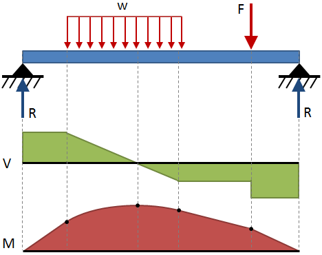
The Ultimate Guide to Shear and Moment Diagrams ... 4.0 Building Shear and Moment Diagrams. In the last section we worked out how to evaluate the internal shear force and bending moment at a discrete location using imaginary cuts. But to draw a shear force and bending moment diagram, we need to know how these values change across the structure. Ultimate Guide to Shear Force and Bending Moment Diagrams ... Being able to draw shear force diagrams (SFD) and bending moment diagrams (BMD) is a critical skill for any student studying statics, mechanics of materials, or structural engineering. ... Shear force and bending moment diagram example #1: single point load; Shear force and bending moment diagram example #2: multiple point loads ... Axial, Shear & Moment Diagrams - StructNotes Axial, shear, and bending moment diagrams (AFD, SFD, and BMD) show the internal forces and moments along a structural member. They help determine the material, size, and type of a member given a set of loads it can support without structural failure. Keeping a consistent sign convention is extremely important! We are going to define the positive… Shear and Moment Diagrams - Including The 3 Moment ... Shear and Moment Diagrams Consider a simple beam shown of length L that carries a uniform load of w (N/m) throughout its length and is held in equilibrium by reactions R1 and R2. Assume that the beam is cut at point C a distance of x from he left support and the portion of the beam to the right of C be removed.
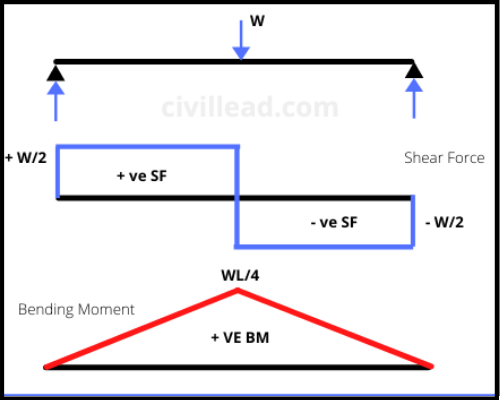
Moment Diagrams: Examples - Cornell University In this example, the point moment causes no shear in the beam, so the shear force diagram is equal to zero. Level 4: Combination! This beam is subjected to both a point load and a constant distributed load. Therefore, three cuts must be made to determine the shear force and bending moment along the entirety of the beam. PDF Statics of Bending: Shear and Bending Moment Diagrams Statics of Bending: Shear and Bending Moment Diagrams David Roylance Department of Materials Science and Engineering Massachusetts Institute of Technology 6.2 Shear/Moment Diagrams - Engineering Mechanics: Statics Below is a simple example of what shear and moment diagrams look like, afterwards, the relation between the load on the beam and the diagrams will be discussed. Source: Internal Forces in Beams and Frames, LibreTexts. DE-12: Lesson 19. SOLVED EXAMPLES BASED ON SHEAR FORCE AND ... Solution: To draw the shear force diagram and bending moment diagram we need RAand RB. Fig. 19.4 Shear force and bending moment By taking moment of all the forces about point A. We get RB× 10 - 8 × 9 - 2 × 4 × 5 - 4 × 2 = 0 RB= 12 kN From condition of static equilibrium ΣFy = 0 RA+ RB- 4 - 8 - 8 = 0 RA= 20 - 12 = 8 kN
web.ncyu.edu.tw › ~lanjc › lessonChapter 4 Shear and Moment In Beams - ncyu.edu.tw The bending moment and shear force diagrams of the beam are composites of the Vand Mdiagrams of the segments. These diagrams are usually discontinuous, or have discontinuous slopes. At the end-points of the segments due to discontinuities in loading. Sample Problem4.1 The simply supported beam in Fig. (a) carries two concentrated loads.
Lesson 12: Drawing Shear and Moment Diagrams Example ... Lesson 12: Drawing Shear and Moment Diagrams Example- Mechanics of Materials and Statics. This is a detailed example of shear and moment diagrams.
PDF Third Edition LECTURE BEAMS: SHEAR AND MOMENT DIAGRAMS ... 2 LECTURE 13. BEAMS: SHEAR AND MOMENT DIAGRAMS (GRAPHICAL) (5.3) Slide No. 2 ENES 220 ©Assakkaf Example 8 (cont'd) A free-body diagram for the beam is shown Fig. 17. The reactions shown on the
beamguru.com › data › examplesDetermining the Shear Force and Bending Moment Equations of ... Structural analysis of statically determinate beams. Define and calculate Shear Force in a beam, draw and calculate Bending Moment in a beam
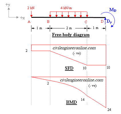
Shear and Moment Diagram Example 3 - Mechanics of ... Shear and Moment Diagram Example 3 - Mechanics of Materials - YouTube Another example of drawing shear and moment diagrams graphically for beam. The beam is loaded with a concentrated moment and a...
PDF Shear Forces and Bending Moments in Beams PDF_C8_b (Shear Forces and Bending Moments in Beams) Q6: A simply supported beam with a triangularly distributed downward load is shown in Fig. Calculate reaction; draw shear force diagram; find location of V=0; calculate maximum moment, and draw the moment diagram. 6k/ft 9 ft RA = (27k)(9-6)/9= 9k A B F = (0.5x6x9) = 27k x = (2/3)(9) = 6 ft
Shear Moment Diagrams: The Best Guide to Using Them ... You now have the tools to begin to make many shear-moment diagrams Other Examples I understand that this is a fairly complicated process, so let's look at some other examples before you're thrown to the wolves. Example 2 - Distributed Load on a Partial Span Building on what we've learned, let's have a distributed load on only a section of the span.
PDF Shear & Moment Diagrams - Mercer University •Draw Shear Diagram -Add point loads, -Integrate distributed loads (w), •Draw Moment Diagram -Integrate shear load, V V (w)dx M Vdx. Example . Example: FBD . Example: look at small section, for 0
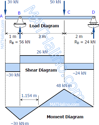
Solution to Problem 403 | Shear and Moment Diagrams ... In segment CD, the shear is uniformly distributed at a magnitude of -24 kN. To draw the Moment Diagram: The equation MAB= -30x is linear, at x = 0, MAB= 0 and at x = 1 m, MAB= -30 kN·m. MBC= 26x - 56 is also linear. At x = 1 m, MBC= -30 kN·m; at x = 4 m, MBC= 48 kN·m. When MBC= 0, x = 2.154 m, thus the moment is zero at 1.154 m from B.
Shear and Moment Diagrams Using Area Method Shear and Moment Diagram Using the Area Method Example 1: Draw the shear and moment diagram of the cantilever beam shown below using the area method. First let's find the reaction forces (apply EoE): Example 1 (cont.'ed): Recall the expressions developed for the area method: dV = w ( x ) dx dM =V dx ∆V = ∫ w ( x) dx ∆M = ∫ V ( x)dx ...
Mechanics eBook: Shear/Moment Diagrams Shear Diagram : Recall, the shear is the derivative of the moment, dM/dx = V, and thus the moment will be a maximum (or minimum) when the shear is 0. From the shear diagram it is noticed that the shear is zero at x = 0.5 ft and x = 1.5 ft. At those points, the moment is -40 ft-lb (x = 0.5) and 20 ft-lb (x = 1.5).
PDF CE 331, Fall 2007 Shear & Moment Diagrams Examples 1 / 7 CE 331, Fall 2007 Shear & Moment Diagrams Examples 6 / 7 Example Problem 2. (same as Problem 1 except overhang = 7ft) • uniform distributed dead load (wD) = 0.50klfapplied to entire beam • uniform distributed live load (wL) = 1.00klfapplied along either Span 1 only, Span 2 only, or Spans 1 and 2 MD: max MD= 12.46k-ftin "middle" of Span 1
Example 11.5 Draw the normal, shear, and moment | Chegg.com Example 11.5 Draw the normal, shear, and moment | Chegg.com. Engineering. Civil Engineering. Civil Engineering questions and answers. Example 11.5 Draw the normal, shear, and moment diagrams for the shown frame 1.6 k/ft 10 ft x 25 km 10 ft 1-5 ft.
Shear and Moment Diagrams - MATHalino Shear and Moment Diagrams Consider a simple beam shown of length L that carries a uniform load of w (N/m) throughout its length and is held in equilibrium by reactions R 1 and R 2. Assume that the beam is cut at point C a distance of x from he left support and the portion of the beam to the right of C be removed.
PDF Shear and Moment Diagrams - Memphis Shear and Moment Diagrams If the variation of V and M are written as functions of position, x, and plotted, the resulting graphs are called the shear diagram and the moment diagram. Developing the shear and moment functions for complex beams can be quite tedious.
PDF 4. Bending Moment and Shear Force Diagram S.F and B.M diagram (iv) Let us take an example: Consider a cantilever bean of 5 m length. It carries a uniformly distributed load 3 KN/m and a concentrated load of 7 kN at the free end and 10 kN at 3 meters from the fixed end. Draw SF and BM diagram. Page 131 of 429. Chapter-4 Bending Moment and Shear Force Diagram S K Mondal's
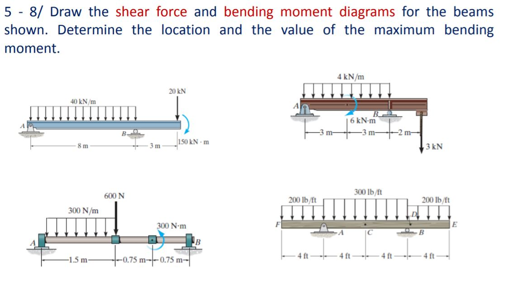


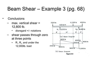







0 Response to "36 shear moment diagram examples"
Post a Comment