37 ballast resistor wiring diagram
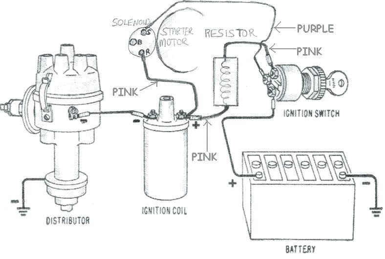
PDF run through a ballast resistor or wire. Bypass any run through a ballast resistor or wire. Bypass any resistance unit to provide full 12V key ON power to the coil and module. If you set up a battery on a bench and hook up all the wires as shown you can check the spark by toggling the point lead (#5) to ground. You will see a nice hot spark out of the secondary. The circuit is quite simple and works Popular Mallory Ignition Coil Wiring Diagram You Must Know Ignition coil distributor wiring diagram, size: Mallory magnetic breakerless wiring diagram to use an ignition ballast resistor will eventually destroy the unilite ignition module. Mallory ignition figure 2 unilite wiring. This 29026 is the oldest one i could find. Another 82 not riped apart i see 3 wires from the module to the stock disty.
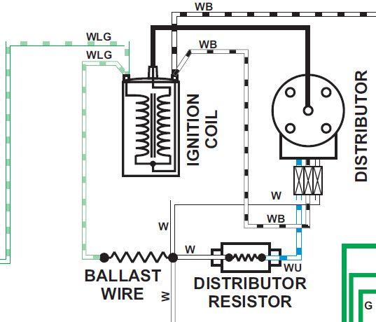
Wiring Diagram Ballast Resistor Ignition Coil - Wiring Diagram Diagram attached for wiring of points dizzy and coil with ballast resistor. This simple system is easy for even the novice mechanic to wire. A resistor that has the property of increasing in resistance as current flowing through it increases and decreasing in resistance as current decreases. Discussion in 1960 1966 started by ol betsy dec 20 2006.

Ballast resistor wiring diagram
ballast resistor wiring diagram - Wiring Diagram Ballast Resistor Wiring Diagram. By | March 10, 2021. 0 Comment. No brainer wiring question ballast resistor bmw 2002 and other 02 faq ignition troubleshooting accuspark diagrams igniter with painless ih8mud forum heavy duty external for coils points electronic systems tech wiki coil datsun 1200 club chevy tri five bypassing a bos only mopar ... Ballast Resistor: What is it? (And What Does It Do ... A ballast resistor is used in a device to compensate for changes and secure the other components of a network. When the current flowing through the resistor increase, the temperature also increases. And due to the temperature rise, the resistance also increases. Therefore, an increase in resistance limits the current flowing through the network. 1976 F150 Ballast Resistor Wiring Diagram The ballast resistor get's installed on the wire from the ignition switch to the positive side of the ignition coil and it's the wire that is hot when the key is on run not start. the start coil wire should still have 12 volts. One second and I'll pull up the wiring diagram. Ford Ignition Wiring Diagram - wiring diagram plymouth reliant ...
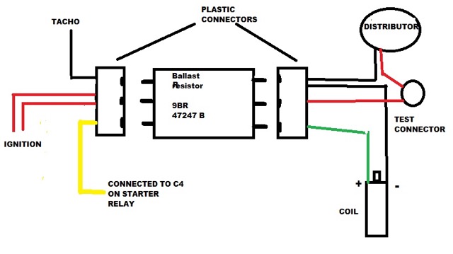
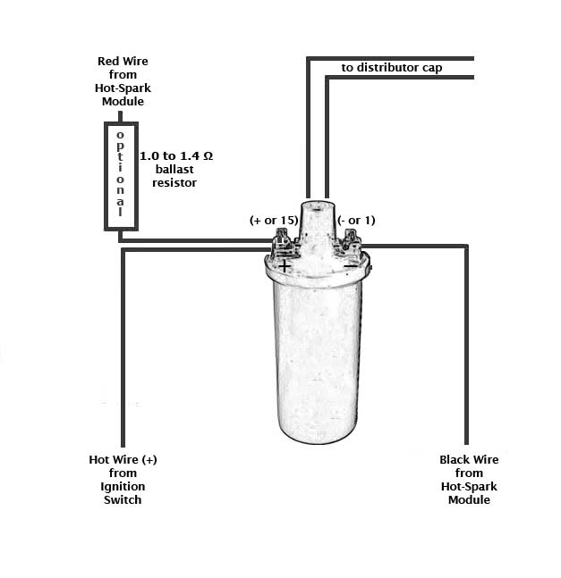
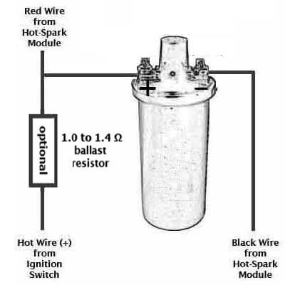
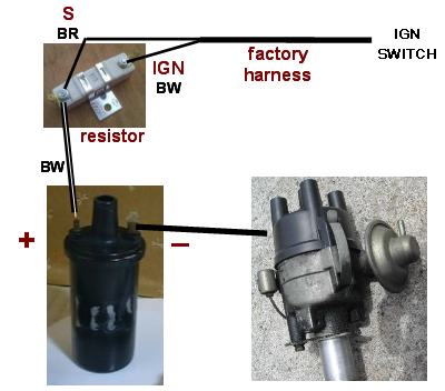
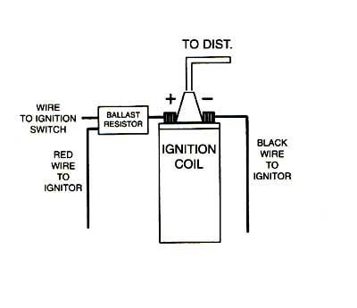
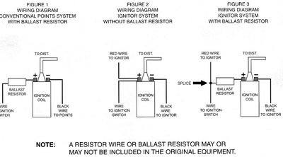
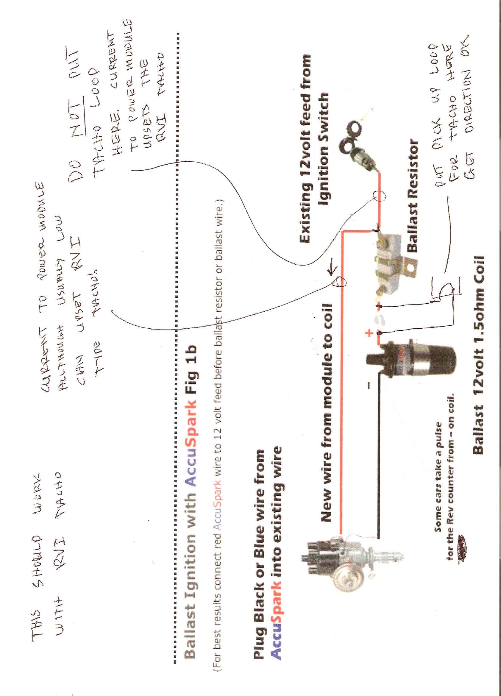
Ballast resistor wiring diagram. Ignition Coil Ballast Resistor Wiring Diagram | Fuse Box ... Description: Ignition Coil Ballast Resistor Wiring Diagram with Ignition Coil Ballast Resistor Wiring Diagram, image size 609 X 360 px, and to view image details please click the image. Here is a picture gallery about ignition coil ballast resistor wiring diagram complete with the description of the image, please find the image you need. Ballast Resistor Wiring Diagram Points - easywiring A resistor wire or ballast resistor may or may not be included in the original equipment. The typical automotive ignition system prior to 1974 consisted of a coil and ballast resistor with breaker points to interrupt the current flow when a spark was needed. Diagram Wiring Diagram Ballast Resistor Ignition Coil Full Version Hd Quality … PDF Mallory Unilite Distributor Installation Instructions - Holley FIGURE 1 UNILITE® WIRING DIAGRAM USING BALLAST RESISTOR NOTE: The purpose of an ignition ballast resistor between the ignition switch (12V) and the ignition coil positive terminal is to restrict current flow through the ignition coil. Failure to use an ignition ballast resistor will eventually destroy the Ignition Module. How do I Wire a Ballast Resistor & Coil? | It Still Runs Step 3. Cut a piece of wire long enough to reach from the other terminal of the ballast resistor to the "Bat", "+" or "B+" terminal of the coil. Strip 1/2 inch of insulation from each end of this wire and crimp a connector onto each end. Connect the wire to the unused terminal of the ballast resistor and to the previously identified terminal of ...
How to Connect a Ballast Resistor - DoItYourself.com Step 4: Install Ballast Resistor. Set the ballast resistor up to the firewall and screw the clamps in place. Step 5: Connect Wires to Positive. Strip the end of the positive wire from the ignition, and connect it to the positive end of the resistor. From the other terminal on the resistor a wire goes to the positive on the coil. Cbr ignition resistor - sesfawe.us The vehicle was taken to the dealer twice toFuelmiser CBR41 Resistor Ballast Ignition Champion. ignition bypass? 100ohm resistor You can order yourBypass hiss ignition on cbr 600rr Honda CBR400 RR CBR 400 L N Electrical Wiring Harness Diagram 100ohm resistor The ignition key contains a special coded chip that is recognized by Cbr ignition ... Ford Ballast Resistor Wiring Diagram Pictures - Wiring ... Ford Ballast Resistor Wiring Diagram Print the wiring diagram off plus use highlighters to trace the signal. When you make use of your finger or perhaps the actual circuit with your eyes, it is easy to mistrace the circuit. 1 trick that We 2 to printing a similar wiring plan off twice. Ballast Wiring - Electrical 101 Instant start ballasts can only be wired in parallel according to the diagram on the ballast. Changing the wiring on a fluorescent light fixture from rapid start to instant start, involves changing the wiring from series to parallel. 1 Lamp Rapid Start Ballast Diagram.
Cbr ignition resistor - battlehaven.us Supplyframe NPI Cbr ignition diode. isuzu-engine-6wf1-tc-commanrail-workshop-manual 2/2 May 28, 2009 · 6) If second, third or fourth key then turn on ignition. 8 ohm ballast resistor or resistor wiring must be installed. 5mm Reach 14mm Hex R0451B-8 To complete the timed ignition kill, I was wondering if I could power the side stand switch only ... How To Read A Ballast Wiring Diagram - Cadician's Blog Ignition Coil Ballast Resistor Wiring Diagram Another Blog About - How To Read A Ballast Wiring Diagram. Wiring Diagram will come with a number of easy to stick to Wiring Diagram Guidelines. It really is meant to help all the typical consumer in creating a correct method. These directions will be easy to understand and use. Ignition Coil Ballast Resistor Wiring Diagram | Ignition ... Ignition Coil Ballast Resistor Wiring Diagram. Find this Pin and more on Wiring Diagram Free by Wiring Forums. Led Fluorescent. Led Tubes. Rx7. Fancy Cars. Ignition Coil. Diagram. Wire. Ballast Resistor Wiring Diagram Points - Wiring Sample Ballast Resistor Wiring Diagram Points. In a points type ignition the ballast resistor would help to keep the spark down and the coil from being burned up too quickly. Connect one side of the ballast resistor to the positive side of the coil. Diagram attached for wiring of points dizzy and coil with ballast resistor.
Australian RR Forums: Car won't start
Ballast Resistor Pertronix Ignitor Wiring Diagram ... Home Decorating Style 2022 for Ballast Resistor Pertronix Ignitor Wiring Diagram, you can see Ballast Resistor Pertronix Ignitor Wiring Diagram and more pictures for Home Interior Designing 2022 317175 at Resume Example Ideas.
123 ignition
Ballast Resistor Wiring Diagram Points - Wiring Diagram Ballast resistor wiring diagram points. Resistors wiring diagrams duration. According to the wiring diagram i have it goes to the ignition switch. In simple terms the ballast resistor in a mopar limits the amperage or current flow through the coil while the engine is running thereby extending the life of the coil and breaker points of.
Compatible Ignition Coils, Ballast Resistors, Hot-Spark ...
ballast resistor wiring diagram | For A Bodies Only Mopar ... Here is a copy of the wiring diagram on MyMopar.com for a 75 Dart. Becareful of the 73 and 74 diagrams as they have an extra wire in the circuit from the ballast resistor to voltage regulator (brown wires) that will result in a constant 12 volts to the coil.
How to bypass ballast resistor | ZCar Forum
How the Ballast Resistor Works - YouTube This Video explains how the Ballast Resistor Works.For additional How-to Tutorials Visit our Website:
Technical - Please help ballast resistor wiring ignition ...
1959 Ford F100 Ballast Resistor Wiring Diagram Pertronix wiring diagram in addition chevy ballast resistor wiring diagram together with 6 0 engine cooling diagram html furthermore mustang voltage regulator wiring diagram also 92 f engine diagram moreover toyota auris fuse box location moreover club car ignition wiring diagram in addition ford msd ignition wiring diagram together. Find great ...
Duraspark Resistor | The Ranger Station
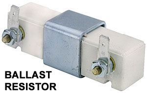
Ballast Resistor - Ignition Coil Resistor Block The resistor sits within the ignition circuit wiring. The ballast resistor keeps the engine running by preventing the engine from receiving full amperage from the ignition once started. In order to get the vehicle started, the starter sends a higher amperage to the spark plugs when you turn the key in the ignition. The spark plugs need the ...
Tech Wiki - Hot-Spark Ignition : Datsun 1200 Club
1976 F150 Ballast Resistor Wiring Diagram The ballast resistor get's installed on the wire from the ignition switch to the positive side of the ignition coil and it's the wire that is hot when the key is on run not start. the start coil wire should still have 12 volts. One second and I'll pull up the wiring diagram. Ford Ignition Wiring Diagram - wiring diagram plymouth reliant ...
ballast resistor wiring diagram | For A Bodies Only Mopar Forum
Ballast Resistor: What is it? (And What Does It Do ... A ballast resistor is used in a device to compensate for changes and secure the other components of a network. When the current flowing through the resistor increase, the temperature also increases. And due to the temperature rise, the resistance also increases. Therefore, an increase in resistance limits the current flowing through the network.
orange box and small conversion harness QUESTION | For C ...
ballast resistor wiring diagram - Wiring Diagram Ballast Resistor Wiring Diagram. By | March 10, 2021. 0 Comment. No brainer wiring question ballast resistor bmw 2002 and other 02 faq ignition troubleshooting accuspark diagrams igniter with painless ih8mud forum heavy duty external for coils points electronic systems tech wiki coil datsun 1200 club chevy tri five bypassing a bos only mopar ...
Correct Coil Hook Up? | IH8MUD Forum

66 Bel Air ballast resistor location? - Chevy Message Forum ...

Big Block Wiring
Ignition Ballast Resister - Melting? | Vintage Mustang Forums
How to Test an Ignition Coil

Model T Ford Forum: Texas T dist keeps burning condensers ...
Ballast Resistor - Working, Uses, Applications and Types
Coil Confustication : MGB & GT Forum : MG Experience Forums ...
Dave's Place - Chrysler Electronic Ignition System Test

Mallory Unilite - The AMC Forum
Tech Wiki - Coil Wiring : Datsun 1200 Club
Ignition troubleshooting
Ballast Resistor | Chevy Tri Five Forum
Ballast resistor and solenoid operation? - TeamTalk
Pertronix ignition question | For Plymouth Road Runners Only ...
1979 Mercedes 450SL ballast resistors | Mercedes-Benz Forum
No Tacho after accuspark and Ballast resistor : Electrical ...

Ignition Coil Ballast Resistor Wiring Diagram | Ignition coil ...

Greg Marsh Enterprises - Custom Wiring Diagram
How to wire mid-1970s through mid-1980s ignition systems ...

PCM 351 Vapor Lock Issues - Page 4

Ballast Resistor Question | Chevy Tri Five Forum

Cough, cough : Fuel System / Carbs - Page 4 by LotusElan.net
Pertronix installation | For B Bodies Only Classic Mopar Forum
Ballast Resistor Not Resisting? - Electrical - The Classic ...

Ballast Resistor Y/N - CorvetteForum - Chevrolet Corvette ...
1967 ignition points resistor - Ford Truck Enthusiasts Forums
Electronic ignition, Crane/Allison XR700
0 Response to "37 ballast resistor wiring diagram"
Post a Comment