39 defrost timer wiring diagram
› refrigerator-repair-5Fridge Compressor Not Working, Refrigerator Not Running Place a screwdriver in the advancement pinion and advance the timer manually (remember, clockwise only) about 1/4 to 3/8 of a turn. Does the compressor start? If it does, replace the defrost timer. If this does not start the compressor, make sure you leave the timer in the "run" mode for the rest of your diagnosis. Go to section 5-3(b). Freezer Defrost Timer Wiring Diagram Defrost Timer Wiring Diagram, furthermore 2 2 ecotec timing marks diagram together with wiring diagram for intermatic t pool pump along with refrigerator ptc relay furthermore walk in freezer defrost timer wiring diagram together with dodge ram radio wiring diagram furthermore domestic refrigerator wiring as well as plant cell.
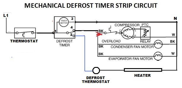
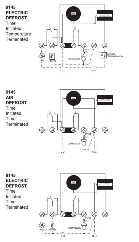
Defrost Termination Thermostat Wiring Diagram Defrost Termination Thermostat Wiring Diagram In a common wiring diagram for a time-initiated, temperature-terminated electric defrost system the time motor (TM) is energized continuously. Is there a reason they can't include a wiring diagram of the switch in the interlink 3 wire defrost termination switch with black and blue wires in.
Defrost timer wiring diagram
PDF 9145 / 9045 UNIVERSAL Series DEFROST TIMERS DEFROST TIMERS An ISO 9001 - 2008 Certified Company Features and Benefits The Paragon® 9045-00 and 9145-00 Universal Defrost Timers are the only multi-voltage defrost timers engineered to refrigeration standards. At four defrosts per day, the Paragon Universal Defrost Timer switches last 16 years longer than competitive offerings. • Real ... PDF Timer motor circuit DEFROST SYSTEMS timer only advances when the compressor is running. After the timer measures an accumulated run time equal to a predetermined amount, the system will enter into the defrost cycle. This type of defrost is often referred to as a cumulative run-time defrost. Even the cumulative defrost systems fail to account for the number of times the door is opened mccombssupply.com › heat-pump-defrost-controlHeat Pump Defrost Control Board for Carrier | McCombs Supply ... Test Time: To enter defrost, short speedup pins for 5 seconds and release ASC Test: Short speedup pins for 1 second and release * Cutting resistor "R50" will disable the ASC timer . Specifications: Voltage: Line 18-30 VAC, 50/60Hz ; Power Consumption: 1 Watt maximum ; Current Draw: 300mA maximum ; Complete with installation guide, wiring diagram.
Defrost timer wiring diagram. Paragon Timer Wiring Diagram For Freezer - Wire Walk in freezer defrost timer wiring diagram wiring diagram is a simplified suitable pictorial representation of an electrical circuit it shows the components of the circuit as simplified shapes and the skill and signal associates together with the devices. Paragon defrost timer wiring diagrams auto electrical wiring diagram. Walk In Freezer Defrost Timer Wiring Diagram Wiring Diagram - Freezer ½ to 2 HP Single Phase. .. Set the correct time of day on the defrost timer. Do not set a cooler thermostat below the walk-ins design temperature or product Diagram 9 - Typical Wiring Diagram for Single with Defrost Timer Only.Jul 02, · I can increase the defrost time (Grasslin timer), but don't believe it will be ... Paragon 8145 20 Defrost Timer Wiring Diagram - easywiring Paragon 8145 20 defrost timer wiring diagram. It reveals the elements of the circuit as simplified forms and also the power and also signal connections between the tools. Collection of paragon defrost timer 8145 20 wiring diagram. 8047 20 208 240 for electric heat defrosting auxiliary contact models 50 hz available open open closed 4 110 min. Timer Wiring Diagram Manual - Wiring Diagram and Schematic ... Tork Rz307 Timers Digital Lighting Timer Guide Manualzz. Hager Eh 010 Timer Instruction Manual Manualslib. 2510sxt Wiring Diagram Hydrotech Sxt Timer User Manual Page 20 24 Original Mode. Paragon 632 20 Defrost Timer. Eapl Model A1d1 On Power Application Preset Timing Starts And At. Clock Timer Wiring Diagram And Setting Home Appliances Parts ...
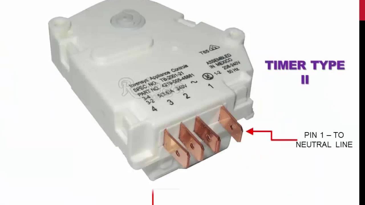
cb-saar.de › dehumidifier-parts-diagram54 parts available. Thanks to its 4-wheel design, you can ... 2 days ago · A wiring diagram for parts of an electric guitar, showing semi-pictorial representation of devices arranged in roughly the same locations they would have in the guitar. Whirlpool Ad50gusx 50 Pint Dehumidifier Instructions Whirlpool Dehumidifier Ad50gusx Manual Recognizing the habit ways to get this books whirlpool dehumidifier ad50gusx manual ... › repair-fix › refrigeratorRefrigerator Not Working | Refrigerator Troubleshooting & Repair Jan 26, 2021 · Normally, the defrost timer cycles the refrigerator to defrost for about 20 minutes every six to eight hours—it essentially heats up coils to melt the ice. If it isn’t working right, ice remains on the tubing and, eventually, restricts airflow through the refrigerator. You can manually advance the defrost timer with some refrigerators. Paragon Defrost Timer 8145 20 Wiring Diagram Find solutions to your paragon defrost timer 20 wiring diagram question. Get free help, tips & support from top experts on paragon defrost timer Adjustable Defrost Cycle Duration: 4 to minutes in S and Paragon Wiring Diagrams Electric Heat Defrosting S & S Series. how to test paragon 20 defrost timer rh waterheatertimer org Paragon 20 Wiring Schematic Paragon Time Clock tors, Paragon ... PDF 8000 MECHANICAL Series DEFROST TIMER - Everwell Parts Applications and Wiring Diagrams MECHANICAL DEFROST TIMER 8000 Series Customer Service Telephone 1.800.304.6563 Customer Service Facsimile 1.800.426.0804 HVACCustomerService@robertshaw.com ©2014 Robertshaw 09/14 - 150-2230 RevB For Technical Service Telephone 1.800.445.8299 Facsimile 1.630.260.7294
Commercial Defrost Timer Wiring Diagram - Using Defrost ... Commercial Defrost Timer Wiring Diagram - Using Defrost Termination And Fan Delay Controls Achr News /. Are the horizontal vane and the vertical vane installed correctly? If your meter reads the proper voltage, then the timer board is good and is supplying power to the gear motor relay or circuit. 29.08.2021 · is the on timer set? PDF Defrost Time Controls / HVAC/R - Neuco defrost timer shall incorporate voltage monitoring to protect against low-voltage conditions. The defrost timer shall also incorporate a short cycle delay adjustable from 0 sec. (off), 6 sec. minimum to 10 min. max to prevent rapid compressor cycling. The defrost timer shall be housed in a UL Type 3R indoor/ outdoor plastic enclosure. controltrends.org › wp-content › uploadsCommercial Refrigeration Temperature and Defrost Controls The Latest Paragon® Defrost Timer • Universal Defrost Timers (UDT) • Works with multiple voltages • Removes built up of ice and frost • Easy to install • Simple to program • Part 9145-00 temp terminated • Part 9045-00 time terminated • Available as mechanism only without case – Add “M” to end of part number Paragon Defrost Timer 8141-20 Wiring Diagram The Latest Paragon® Defrost Timer • Universal Defrost Timers (UDT) Universal Defrost Timer - Wiring. Convert to Convert to Convert to N 1 4 32 X. Jun 20, · They are both commercial as well. I know when we draw up the schematic diagram the position of N and X are different.
Part Number: E108318_S
Samsung Refrigerator Defrost Timer Wiring Diagram ... Samsung Refrigerator Defrost Timer Wiring Diagram Free Download 2022 by mervin.ryan. Find The BestTemplates at vincegray2014.

SOLVED: Trying to replace a 8045-20 w/ 8145-20 need wiring ...
Defrost Termination Thermostat Wiring Diagram I got there and found no diagram on the unit, and no stat like that in the truck, the evap solid ice, and no common to the defrost heaters. Somebody 'fixed' it . 3 Wire Defrost Termination Switch Diagram - Defrost termination switch wiring diagram together with paragon 00 defrost timer wiring diagram as well as simple limit switch diagram ...
How To Test the Defrost Timer - Refrigerator Repair Guide ...
refrigerator defrost timer wiring diagram - Wiring Diagram ... Sketch Wiring Diagram Of Dwelling House Pour Android Téléchargez L. Precision Multiple Controls Official Website Your Source For Energy Saving Photocontrols. China Supco Heavy Duty 8 Hours 25 Minutes Refrigerator Tmdc Defrost Timer 825 1 And. Fixed Frigidaire Mini Refrigerator Defrost Timer Replacement Help W10822278 Uet120 Dbyc903bl Page 3 ...

Diagram Page
Wiring Diagram Frigidaire Defrost Timer 21546602 FOR FRESH FOOD THERMISTOR AND DEFROST THERMISTOR. °F Operating Time.defrost. With the notch on the timer knob aligned with the line on the bracket (Fig. A), turn the defrost timer knob clockwise slowly. The timer will click several times, then once loudly, at which point the defrost cycle begins.

Defrost Timer - Electrical & In-Line Components - Parts ...
› Models › FRT17G4BW9FRT17G4BW9 Frigidaire Refrigerator Parts & Repair Help ... The defrost timer was first, but that did not fix it. To do this I had to remove the ice maker and the back plate of the freezer. Then I defrosted the coil and cut the wires. stripped them back and installed the new thermostat. re-assembled and tested. has been working great ever since.

Domestic Refrigerator Wiring | Electrical wiring diagram ...
W10822278 Wiring Diagram W10822278 Wiring Diagram. Kenmore Refrigerator Defrost Timer W - This eight-hour defrost timer So I figured my model was too old, the wiring diagram was simalar to mine on. I do not have a wiring diagram. ANSWER Hello Ken, You will need to connect the black jumper wire on the defrost timer W to pin. Whirlpool W Refrigerator Defrost Timer ...
Defrost Time Controls / HVAC/R Defrost Time Controls / HV AC/R
Whirlpool Refrigerator Defrost Timer Wiring Diagram ... Paragon Defrost Timer Wiring Diagram. Ge Refrigerator Wiring Diagram Defrost Heater. Whirlpool Refrigerator Wiring Diagram Pdf. Whirlpool Refrigerator Wiring Diagrams. Whirlpool Gold Refrigerator Diagram. Whirlpool Refrigerator Water Line Diagram. 3 Wire Defrost Termination Switch Wiring Diagram. 8 Pin Timer Relay Wiring Diagram.
Older Frigidaire defrost timer - DoItYourself.com Community ...
Paragon Timer Wiring Diagram - schematron.org The Paragon® Series Auto Voltage Defrost Timer is designed competitive voltage-specific mechanical defrost timers, eliminating Wiring Diagrams. Simple wiring. Resources: Paragon sell sheet shows model numbers and wirings diagrams, Replace with TT or CT series.

Typical wiring for defrost on a single evaporator freezer
PDF WIRING DIAGRAM - AboveAir DEFROST TIMER WIRING DIAGRAM SPECIFICATIONS Input • Voltage: 18-30 VAC • Frequency: 50-60 Hz • Power Consumption: 1 watt maximum Output • O, W2: - Type: Relay - Form: DPST, normally open - Rating: 2 amps @ 30 VAC • DF1, DF2: - Type: Relay - Form: SPST, normally closed - Rating: 1/2 HP @ 240 VAC Time Delays

Intermatic Defrost timers and manuals
Wiring Diagram Frigidaire Defrost Timer 21546602 Domestic Refrigerator Wiring Determine. defrost. With the notch on the timer knob aligned with the line on the bracket (Fig. A), turn the defrost timer knob clockwise slowly. The timer will click several times, then once loudly, at which point the defrost cycle begins.
Defrost Timer - Electrical & In-Line Components - Parts ...
Grasslin Dtav40 Wiring Diagram Grasslin Dtav40 Wiring Diagram. For electric heat, hot gas or compressor shutdown defrost. The Grässlin DTAV40 Series Auto Voltage Defrost Timer is applicable to air defrost (compressor. Intermatic/Grässlin's Defrost controls just got even better! The DTAV40 defrost control automatically selects the appropriate voltage between Wiring Diagrams .
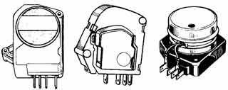
TIMERS FOR REFRIGERATOR TYPE NO FROST
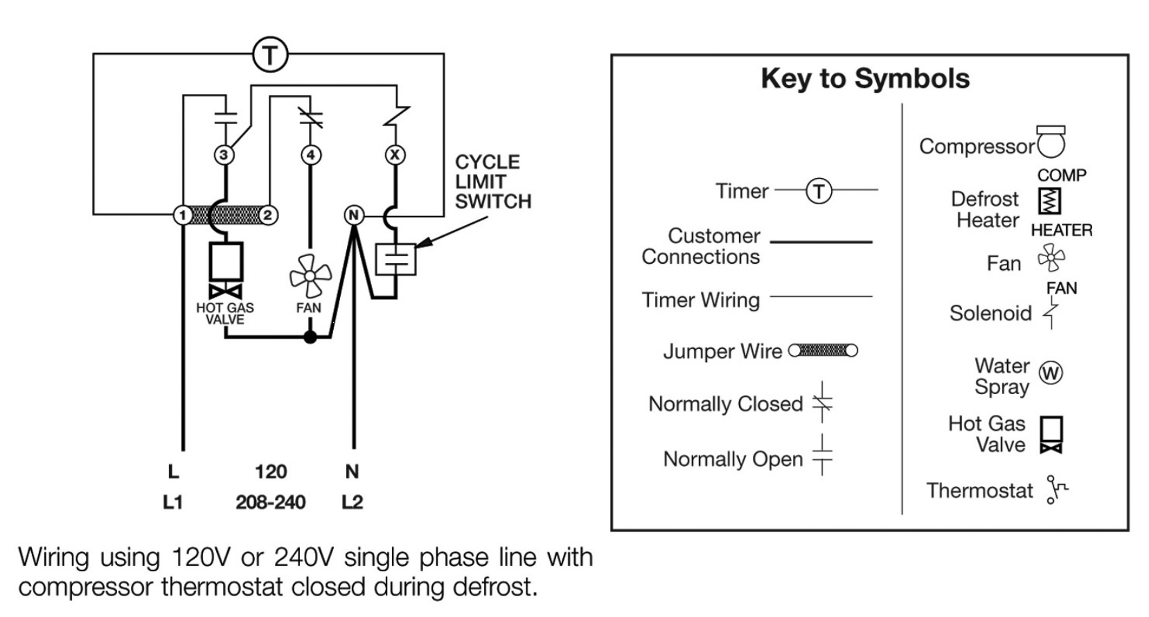
Paragon Defrost Timer Wiring Diagram Wiring Diagrams Paragon Defrost Timer Wiring Diagram On the timer wheel, choose a defrost cycle starting time. 2. Slide the the wiring diagram chosen. . Robertshaw®, Paragon® and Uni-Line® are trademarks of. Defrost Timer Controls. - Series Defrost Typical line voltage wiring diagram. 3. Determine Paragon® Universal Defrost Timer (UDT).

defrosttimer - YouTube
Paragon Defrost Timer Wiring Diagram - Wiring Systems Paragon defrost timer wiring diagram. Paragon sell sheet shows model numbers and wirings diagrams Replace with TT or CT series. The Paragon defrost and the Tork electric timers. I cant seem to find a wiring diagram on how to wire this correctly Link below has wiring diagrams and wiring. Paragon Defrost Timer 8141-20 Wiring Diagram.

Originele Luchtgekoelde Koelkast Timer/Luchtgekoelde ...
› refrigerator-repair-3Refrigerator Wiring Diagram Repair, Electrical Circuit Diagram After fixing a defrost problem, keep an eye out for signs of a recurrence for at least a week. The sooner you catch it, the less ice you'll have to melt. 7) You may stop the compressor from running using the defrost timer or cold control, by cutting off the power to the fridge, or simply by pulling the plug out of the wall.

Walk-In Cooler Defrost - HVAC School
Walk In Freezer Defrost Timer Wiring Diagram In a common wiring diagram for a time-initiated, temperature-terminated Normally closed contacts of the defrost timer are wired in series. OUTDOOR WALK-IN COOLERS AND FREEZERS . Wiring Diagram - Freezer ½ to 2 HP Single Phase. .. Set the correct time of day on the defrost timer. Defrost Timer Controls.
Refrigerator Defrosting timer full connections and test timer in urdu/hindi
Paragon Defrost Timer 8145-00 Wiring Diagram Then timer outputs can control 3-phase power using 3-phase contactors Contactor below is 3 phase with V coil http: Link below is for Paragon commercial box-type defrost timers http: I cant seem to find a wiring diagram on how to wire this correctly Link below has wiring diagrams and wiring manuals for V http: According to information from ...
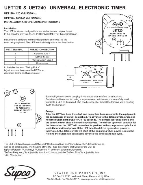
Installation & Operating Instructions - Supco
mccombssupply.com › heat-pump-defrost-controlHeat Pump Defrost Control Board for Carrier | McCombs Supply ... Test Time: To enter defrost, short speedup pins for 5 seconds and release ASC Test: Short speedup pins for 1 second and release * Cutting resistor "R50" will disable the ASC timer . Specifications: Voltage: Line 18-30 VAC, 50/60Hz ; Power Consumption: 1 Watt maximum ; Current Draw: 300mA maximum ; Complete with installation guide, wiring diagram.
FIXED - FRT045GM Defrost Timer Question | Page 2 ...
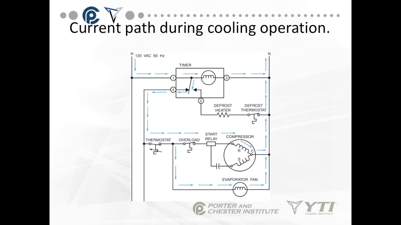
PDF Timer motor circuit DEFROST SYSTEMS timer only advances when the compressor is running. After the timer measures an accumulated run time equal to a predetermined amount, the system will enter into the defrost cycle. This type of defrost is often referred to as a cumulative run-time defrost. Even the cumulative defrost systems fail to account for the number of times the door is opened
Whirlpool Refrigerator Defrost Timer | Appliance Aid
PDF 9145 / 9045 UNIVERSAL Series DEFROST TIMERS DEFROST TIMERS An ISO 9001 - 2008 Certified Company Features and Benefits The Paragon® 9045-00 and 9145-00 Universal Defrost Timers are the only multi-voltage defrost timers engineered to refrigeration standards. At four defrosts per day, the Paragon Universal Defrost Timer switches last 16 years longer than competitive offerings. • Real ...
Defrost Timer (R 8004-TMDE706SC) refrigerator Defrost Timer ...

Diagram circuit: Refrigerator Wiring Diagram Defrost Timer ...

double #door #fridge #wiring #diagram ...
How to test Paragon 8145-20 defrost timer.

Comfort Cool Ref & Aircondition Engineering Service - Posts ...

China Refrigerator Defrost Timer Sankyo Tmde706sc - China ...

Defrost Timers, description about Defrost Timer TMDF702DH1 on ...

DEFROST TIMER 6HR RUN / 30MIN DEFROST 220V : MacSpares ...
Whirlpool Refrigerator Defrost Timer | Appliance Aid

Precision Multiple Controls Official Website - Your Source ...
Commercial Refrigeration Temperature and Defrost Controls
Appliance411 FAQ: How does a Frost Free Refrigerator's ...
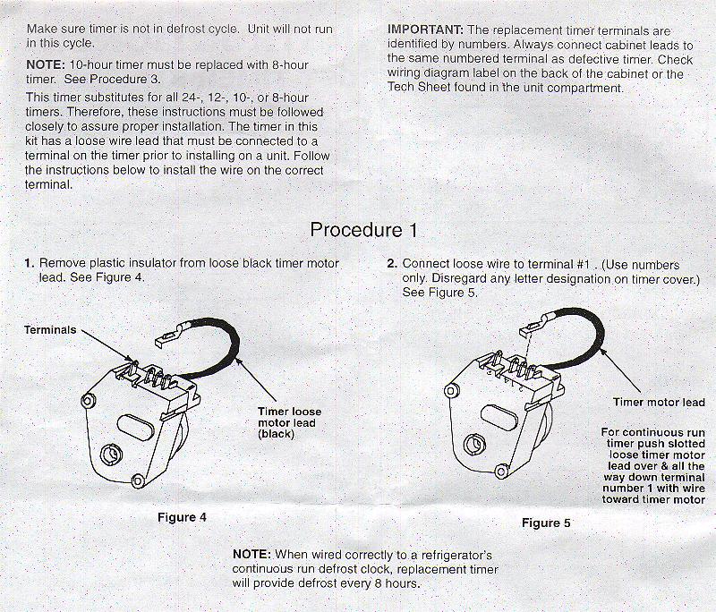
WHIRLPOOL INSTALLATION INSTRUCTIONS FOR 482493 DEFROST TIMER ...
Precision Defrost Timers - Replacements Only

Buy 3081050, 3-08-150-0, 7014648, for Refrigerator Defrost ...
.JPG)
I looking for wiring scheme of defrost timer in old LG ...

Amazon.com: Whirlpool 482493 Defrost Timer for Refrigerator ...

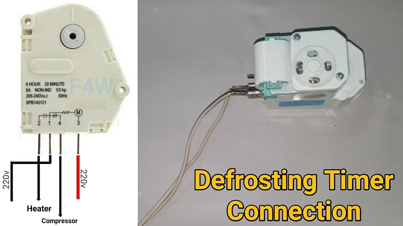
How To Make D-Frosting Timer Heater & Compressor Wiring With Diagram | Fully4Word
PARAGON COMMERCIAL DEFROST TIMER DIGITAL
Core Refrigeration: Domestic Defrost Timer
0 Response to "39 defrost timer wiring diagram"
Post a Comment