39 nmea 2000 wiring diagram
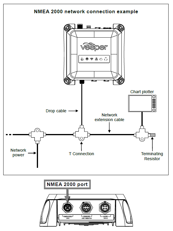
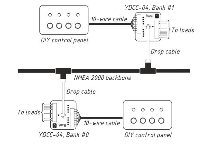
PDF The NMEA 2000 Cables & Connectors - Cactus Nav Maretron NMEA 2000® Cables & Connectors About NMEA 2000® Cables and Connectors The NMEA 2000® standard goes beyond defining message content and includes requirements for the cabling used to interconnect electronic components (referred to as the physical interface). The following catalog pages contain the NMEA 2000® approved network interconnect PDF Installation & User Manual - MBW Tech Step 4. NMEA Network Connection For connection to the NMEA 2000 network the EM2000 provides a NMEA 2000 compliant devicenet connector. This is a round 5 pin connector and connection is made to the backbone by using a CANBus devicenet Tee. If a NMEA 2000 backbone is not currently installed you will need to do so.
PDF Wiring Diagram Field-Attachable DeviceNet Connector Wiring Diagram Field-Attachable DeviceNet Connector NMEA 2000® Compatible Assembling and Wiring the Connector NOTE: The instructions are the same for both male and female connectors. 1. Remove a connector from the bag and unscrew the terminal assembly from the body of the connector (see Figure 1).

Nmea 2000 wiring diagram
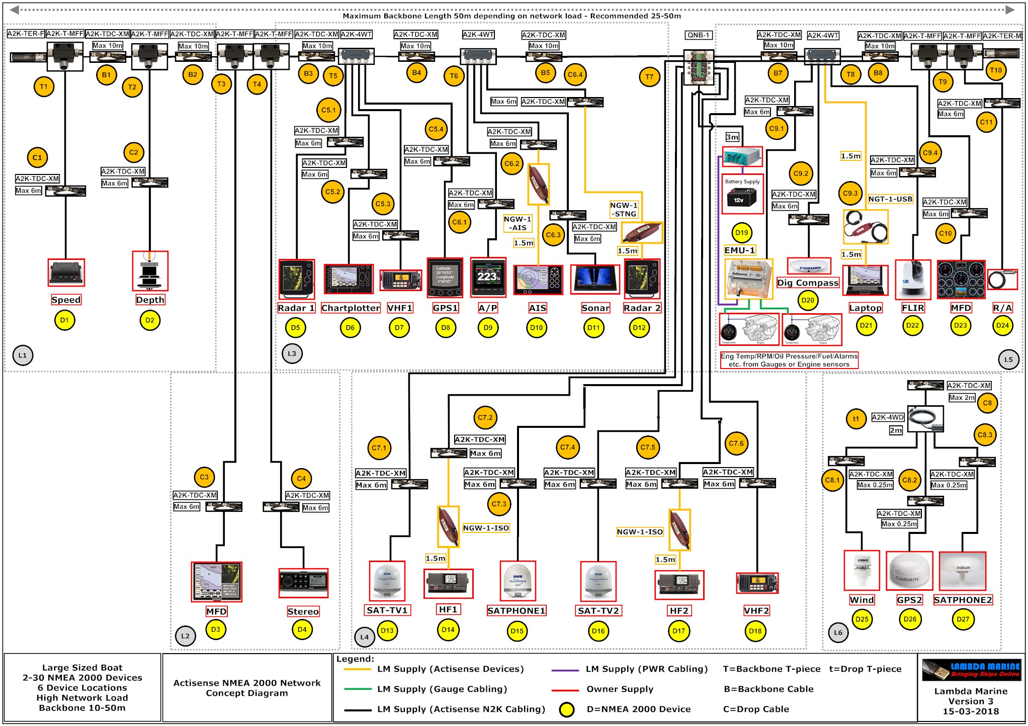
PDF Your complete guide to building an NMEA 2000 network The NMEA 2000 wiring colour system is standardised so the colours and pin numbers will be the same for any wire and connector combination that uses the same DeviceNet standard. Actisense field fit connectors are available as straight or right angled options and in male and female variants to suit any installation requirement. NMEA 2000® - Humminbird NMEA 2000 compatibility is built into all APEX, SOLIX and HELIX G4N models to provide you a full view of your vessel, no matter what control head you have onboard. Additionally, many legacy models from Humminbird can connect to a NMEA 2000 network with a waterproof black-box solution, AS ETH NMEA2K - NMEA 2000 Black Box Adapter. PDF Technical Reference - Garmin The NMEA 2000 components included with a Garmin sensor or display are listed in the product documentation. A diagram on the product box shows which NMEA 2000 components are included. +-Sample Box Diagram (GFS 10) In the sample box diagram, a complete NMEA 2000 network is shown, and the parts included with the sensor are shaded. In this example, a
Nmea 2000 wiring diagram. PDF Nmea 0183 Installation and Operating Guidelines Interfaces between NMEA 0183 or NMEA 0183-HS and an NMEA 2000 ® backbone must be provided using NMEA 2000 ® certified devices intended for that purpose. Opto-isolation and voltage level shift may be required to interface devices designed to communicate using RS-232 with NMEA 0183 compatible devices. Refer to NMEA Nmea 2000 Wiring Diagram Gallery - Wiring Diagram Sample Wiring Diagram Sheets Detail: Name: nmea 2000 wiring diagram - Evinrude Wiring Diagram Outboards - Sinfofo Astonishing Nmea 2000 Wiring Diagram Honda 90 Best Image. File Type: JPG. Source: fidelitypoint.net. Size: 96.66 KB. Dimension: 620 x 432. Lowrance Nmea 2000 Wiring Diagram - schematron.org A wiring diagram is a simplified conventional photographic depiction of an electric circuit. It reveals the parts of the circuit as simplified forms, as well as the power and signal connections in between the devices. Wiring diagram for lowrance nmea furthermore garmin new install no satellite signal also nmea wiring diagram for two screens ... How to Install NMEA 2000 Boat Electronics System - YouTube In this episode we install the wiring necessary for our new electronics package. I go into detail about the NMEA 2000 system and how to install. Then, I flip...
PDF Maretron NMEA 2000 Network Installation Guide Maretron NMEA 2000 ® Network Installation Guide ... The following diagram shows the pins found ... have a shield wire as this connection is made to the screw terminal on the Powertap itself. 3.2 Mini Power Capability Although Mini cable is rated to 8 amps, the cable system can support a total load of more than 8 amps. For example, 16 Garmin Nmea 2000 Wiring Diagram - Wiring Diagram Garmin Nmea 2000 Wiring Diagram. By Admin | November 7, 2017. 0 Comment. Nmea 2000 building an network salt water sportsman installing the garmin gmi 10 display data repeater on a boat fundamental danger of networks quick guide to kus usa panbo marine electronics hub power problem part 2 adrena software off new f200xb page hull truth boating ... PDF NMEA 2000® Engine Interface - Marine Chandlery output engine data with an interface connection to an onboard NMEA 2000® network. This data can be viewed on any multifunction display (MFD) and digital gauge shown below. Contact engine manufacturer for the most current NMEA 2000® compatibility information. Lowrance HDS® Gen2: 5-inch / 7-inch 8-inch / 10-inch Lowrance HDS®: PDF NMEA 0183 NMEA 2000 - furunousa.com NMEA 2000. Figure 6. Wiring diagram. NOTE: One of the butt connectors will be used to connect the three bare wires. (Each connector has 3 holes to accommodate up to 3 wires.) NOTE: The red wire from the sensor cable will be connected to the red wire from the NMEA 2000 cable. Likewise, the black wire from the sensor cable will be connected to ...
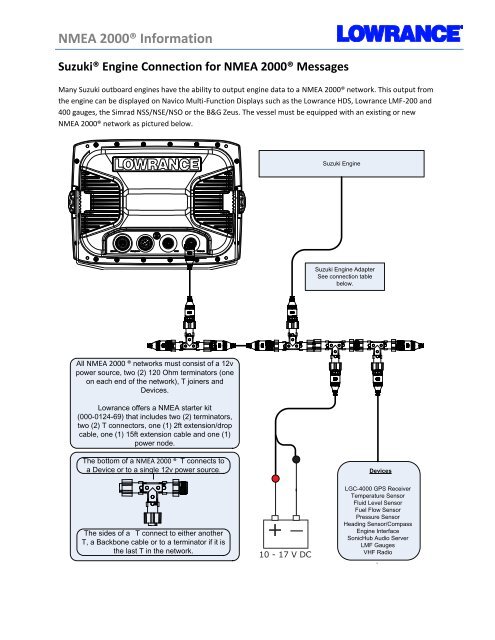
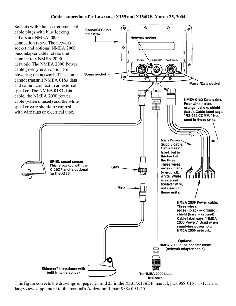
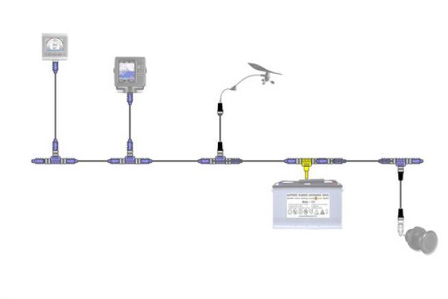
Humminbird Networking Diagrams | Humminbird With these wiring diagrams, you can be confident that you'll start the fish finder install process with all of the cables and accessories you need for your specific boat setup. ... Build your NMEA 2000 backbone and connect your Humminbird® control head with one or more NMEA 2000 devices. Interactive NMEA Network Diagrams - NMEA 0183 & 2000 ... We've created two interactive network diagrams, NMEA 2000 and NMEA 0183, to give you an example of how our award-winning products can be used on a boat's network. NMEA 2000 Network Diagram Explore the network. NMEA 0183 Network Diagram Explore the network. Find a distributor Sign up to our Blog. PDF NMEA 2000 Network Fundamentals - static.garmincdn.com the NMEA 2000 power cable directly to the battery and install an in-line switch. cauTiON: If you connect the NMEA 2000 network to your battery without an in-line switch, it may drain your battery. Be sure to ground the NMEA 2000 power cable. Ground the drain wire (bare) to the same location as the ground wire. Lowrance Nmea 2000 Wiring Diagram Lowrance Nmea 2000 Wiring Diagram. The ability to network over NMEA and Ethernet allows access to data as well .. The following diagram demonstrates a typical small NMEA network: . terms: NMEA Network/LowranceNET, NMEA Bus/Network. Bus, Network .. network that is already powered, see diagram B below.)
Nmea 2000 Wiring Diagram Collection - Wiring Collection Nmea 2000 Wiring Diagram Collection. Assortment of nmea 2000 wiring diagram. A wiring diagram is a simplified conventional photographic depiction of an electric circuit. It reveals the parts of the circuit as simplified forms, as well as the power and signal connections in between the devices. A wiring diagram normally gives information concerning the relative…
Lowrance NMEA 2000 Network Basics - YouTube Lowrance Product Expert Jacob Scott talks about the basics to wiring your NMEA 2000 network, including some tips to avoid common mistakes.Learn more: https:...
PDF Technical Reference - Garmin The NMEA 2000 components included with a Garmin sensor or display are listed in the product documentation. A diagram on the product box shows which NMEA 2000 components are included. +-Sample Box Diagram (GFS 10) In the sample box diagram, a complete NMEA 2000 network is shown, and the parts included with the sensor are shaded. In this example, a
NMEA 2000® - Humminbird NMEA 2000 compatibility is built into all APEX, SOLIX and HELIX G4N models to provide you a full view of your vessel, no matter what control head you have onboard. Additionally, many legacy models from Humminbird can connect to a NMEA 2000 network with a waterproof black-box solution, AS ETH NMEA2K - NMEA 2000 Black Box Adapter.
PDF Your complete guide to building an NMEA 2000 network The NMEA 2000 wiring colour system is standardised so the colours and pin numbers will be the same for any wire and connector combination that uses the same DeviceNet standard. Actisense field fit connectors are available as straight or right angled options and in male and female variants to suit any installation requirement.



![Garmin echoMAP™ 50s [5/42] NMEA 2000 Fundamentals](https://mans.io/views2/1123818/f_page-5.png)




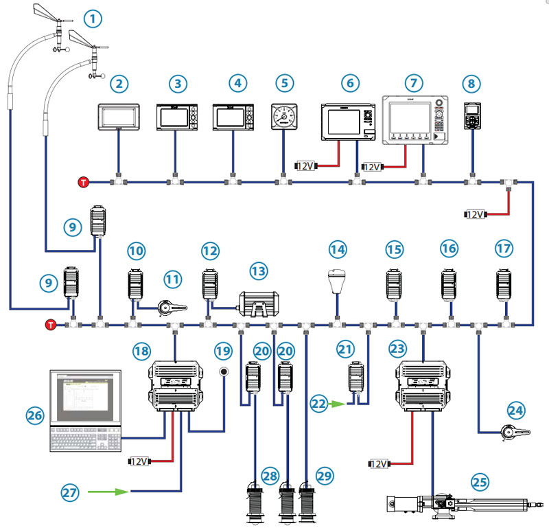


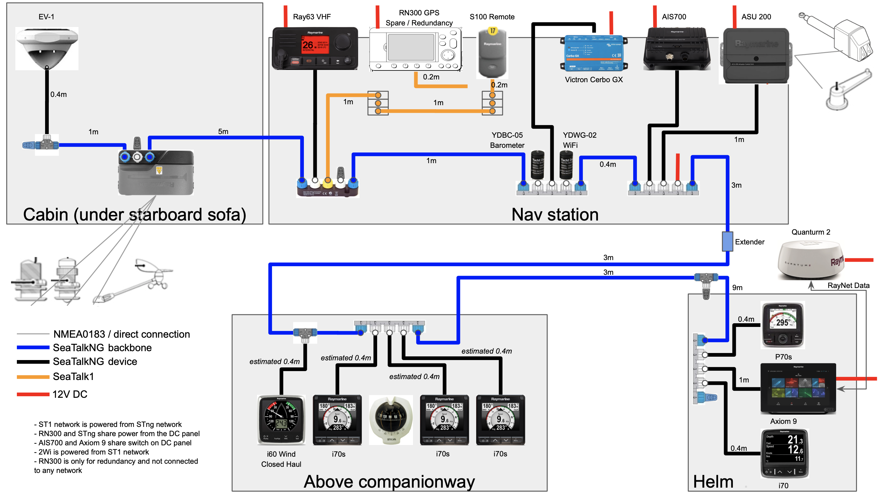
![NMEA 2000 & MFD integration guide [Victron Energy]](https://www.victronenergy.com/live/_media/ve.can:nmea-2000:image_hml5_nmea2k_arrows.png)



0 Response to "39 nmea 2000 wiring diagram"
Post a Comment