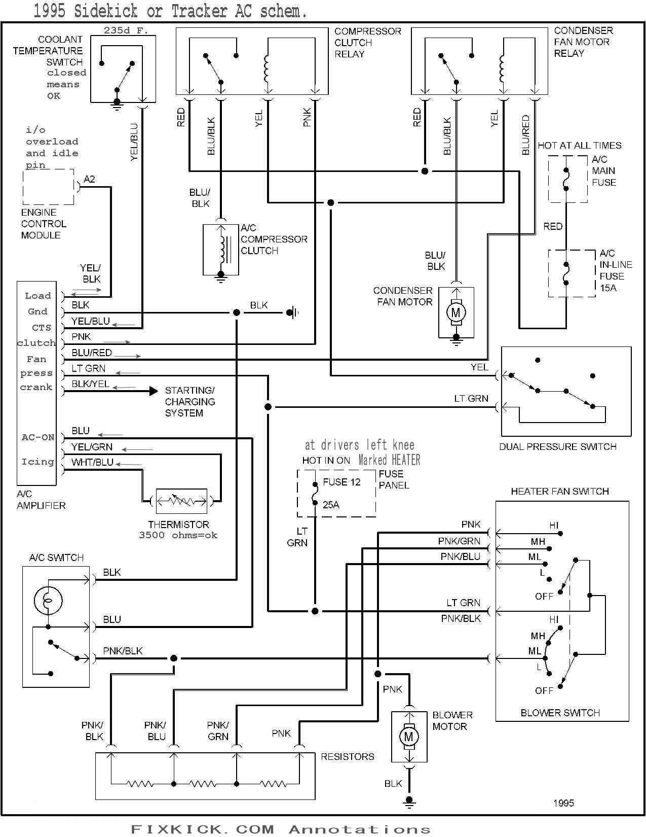
36 hvac condenser wiring diagram
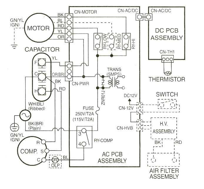
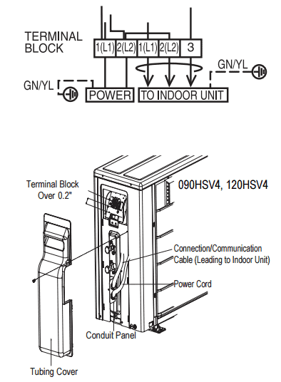
Condenser Low Voltage Wiring - Wiring Diagram The condenser is one of three crucial parts of a home air conditioning system. How to wire an air conditioner for control 5 wires the diagram below includes the typical control wiring for a conventional central air conditioning systemit includes a thermostat a condenser and an air handler with a heat source. Electrical Wiring Diagrams for Air Conditioning Systems ... in Fig.18, you can find examples for the complete wiring diagrams for Multi-split air conditioners. Fig.18: Multi-split air conditioners Electrical Wiring Diagram 4- Mini- Heat Pumps 4.1 The power wiring of Mini- Heat Pumps The power wiring of Mini- Heat Pumps will look like that of the Split air Cooling Units for far extent (see Fig.19).
Trane Condenser Fan Motor Wiring Diagram - schematron.org Trane Condenser Fan Motor Wiring Diagram. Rheem-Ruud Condenser Fan Motor wiring diagram heat pump wiring diagram blower motor wiring heat pump parts ruud air conditioning trane. Orange wire that is the start winding for compressor that goes on HERM. Red wire from contactor goes to C on capacitor, purple from fan goes to C on capacitor.

Hvac condenser wiring diagram
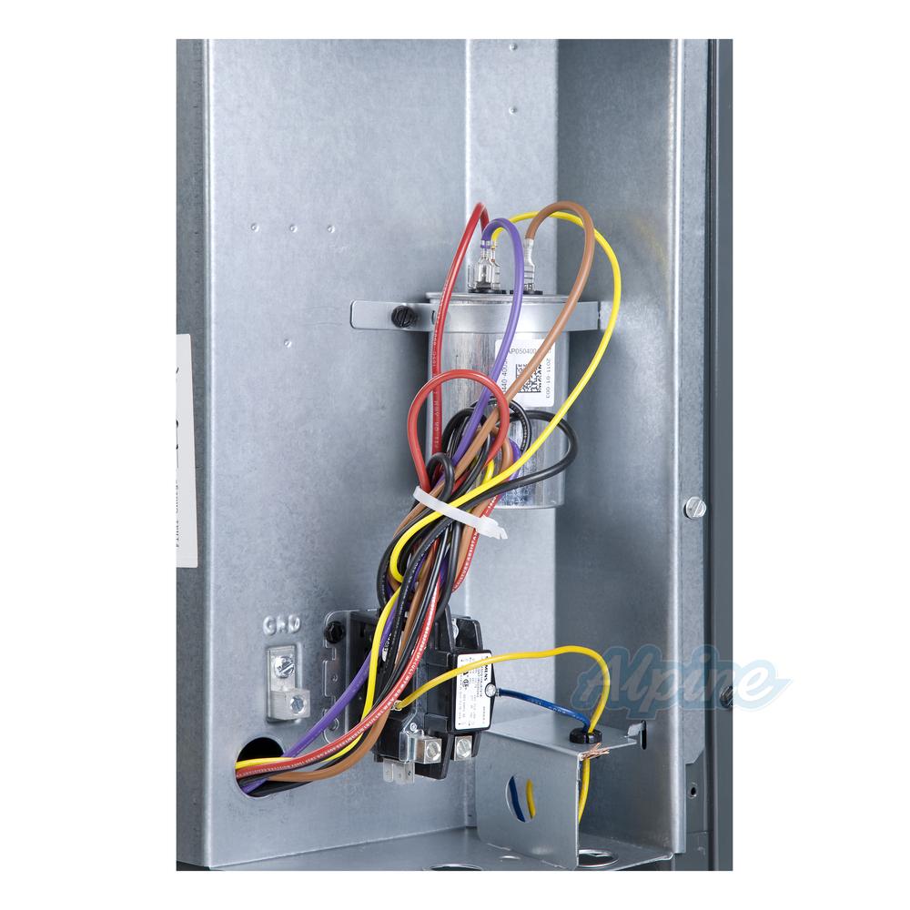
Condenser Capacitor Wiring Diagram - easywiring Examine and understand the condensing unit s wiring diagram usually located on the inside of the service box s cover. For a visual picture of typical wiring configurations reference the following guide. A wiring chart on the fan motor s case also identifies the fan. Not sure how to wire it up. Now the start cap is hot and leaking. How to Wire an Outside AC Condenser - Hunker First, the bare copper ground wire is connected to the ground terminal block, using a flathead screwdriver. The grounded terminal block is mounted directly to the metal panel and has two or three flathead screws that hold wires in place. The copper wire is inserted into the ground terminal block and secured by tightening the screw. Ac Condenser Unit Wiring Diagram - Wiring Diagram How to wire an air conditioner for control 5 wires the diagram below includes the typical control wiring for a conventional central air conditioning systemit includes a thermostat a condenser and an air handler with a heat source. Straight cool air conditioning condensing unit wiring practice. If not the arrangement wont function as it should be.
Hvac condenser wiring diagram. Wiring an Outdoor Condenser! What each of the Wires is For ... This is how to wire a 240-volt single-phase Condenser used for Air Conditioning. This includes where to install the high and low voltage wiring and why, how ... Ac Condenser Wiring Diagram - Cadician's Blog Installing A 5-2-1 Hard Start Capacitor Kit On A Tempstar/carrier - Ac Condenser Wiring Diagram Wiring Diagram contains both examples and step-by-step directions that would enable you to definitely actually construct your undertaking. PDF Standard AC Wiring Diagrams update - Alpine Home Air This diagram is to be used as reference for the low voltage control wiring of your heating and AC system. Always refer to your thermostat or equipment installation guides to verify proper wiring. NOTESome AC Systems will have a blue wire with a pink stripe in place of the yellow or Y wire. 1(800) 865-5931 How To Wire an Air Conditioner Condenser Outside Unit ... Quick video stepping you through how to wire a typical 220v AC condenser unit. Hope it helped you out! Please subscribe!Blessings,Ben
PDF HVAC Condenser Motor Replacement Wiring Guide HVAC Condenser Motor Replacement Wiring Guide Brown ˜˜˜˜˜ Contactor Fan C Herm Capacitor Original Compressor Common L1 L2 Wire Colors May Vary L1 L2 208-230 VAC S R C New Motor & New Capacitor New Capacitor (Non-Polarized) 'F' Terminal is No longer used Brown Brown White Motor Contactor Fan C HERM Capacitor Original Compressor S R C Standard AC Wiring Diagrams .pdf - Alpine Home Air Products This diagram is to be used as reference for the low voltage control wiring of your heating and AC system. Always refer to your thermostat or equipment installation guides to verify proper wiring. NOTESome AC Systems will have a blue wire with a pink stripe in place of the yellow or Y wire. 1(800) 865-5931 Typical Field Wiring and Wiring diagram - Heat & Cool Outdoor Unit Wiring Diagram for A/C Systems(208/230V 1P 60Hz). CC. COMPRESSOR CONTACTOR. RC 1. RUN CAPACITOR 1 ... NOTES: 1.AC:Air Conditioner; HP:Heat Pump.3 pages WIRING DIAGRAM Single Phase. Split System Air Conditioner (Outdoor Section). With Outdoor Fan Relay. Legend. Field Wiring. Factory Wiring: Low Voltage. High Voltage.1 page
Ac Fan Wiring | Wiring Diagram - Ac Condenser Wiring ... Ac Condenser Wiring Diagram - ac condenser contactor wiring diagram, ac condenser fan motor wiring diagram, ac condenser fan wiring diagram, Every electric structure is composed of various different parts. Each component should be placed and connected with different parts in specific manner. If not, the structure will not function as it should be. Ac Condenser Fan Motor Wiring Diagram | Fuse Box And ... Description : Condenser Fan Motor Wiring Diagram in Ac Condenser Fan Motor Wiring Diagram, image size 600 X 559 px, and to view image details please click the image. Here is a picture gallery about ac condenser fan motor wiring diagram complete with the description of the image, please find the image you need. Ac Compressor Wiring Diagram - The Wiring Ac low voltage wiring diagram. Compressor and fan motor furnished with inherent thermal protection. AC System Diagram Before you call a AC repair man visit my Air conditioning unit wiring diagrams fig. Ac compressor wiring diagram. 1—38ck018 (32, 34), 38ck(m)024 (32, 34), 38ck(m)030 (30, 32), 38ck(m)036. Each part should be placed and linked to other […] Thermostat Wiring Diagrams Quality HVAC Guides 101 Thermostat Wiring Diagrams for Heat Pumps - Heat Pump Thermostat Wire Diagrams. Heat pumps are different than air conditioners because a heat pump uses the process of refrigeration to heat and cool.While an air conditioner uses the process of refrigeration to only cool, the central air conditioner will usually be paired with a gas furnace, an electric furnace, or some other method of heating.
How-To Wire Condenser Fan Motors Properly in 3-Wire & 4 ... For a visual picture of typical wiring configurations, reference the following guide: HVAC Condenser Fan Motor Wiring Diagram. Finally, this guide is intended to be used as a general overview of common condenser unit wiring schematics. Some condenser fan motors wire to a circuit board while others use proprietary plugs for their connectors.
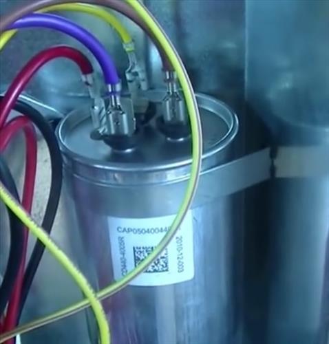
PDF How to Wire a Run Capacitor to a Motor Blower & Condenser ... How to Wire a Run Capacitor to a Motor Blower & Condenser HVAC Wiring The above illustration does not cover every single type of motor wiring available on the market. However, motor and capacitor diagram represents a vast majority of motors and capacitor wiring available to the general public. As always, we
Condenser Wiring Diagram - easywiring Condenser wiring diagram. With this sort of an illustrative manual you are going to be able to troubleshoot prevent and complete your assignments easily. Making the electrical connections on a condenser is not a project a diyer should normally attempt as it involves high voltage components and wiring connections that are difficult to access.
Ac Condenser Wiring Diagram - Wirings Diagram There are two things that will be present in any Ac Condenser Wiring Diagram. The first element is symbol that indicate electrical component in the circuit. A circuit is generally composed by many components. Another thing you will locate a circuit diagram would be lines. Lines in the diagram show exactly how each element connects to a another.
Electrical Wiring Diagrams for Air Conditioning Systems ... 3- Types of Electrical Wiring Diagrams For Air Conditioning Systems There are three basic types of wiring diagrams used in the HVAC/R industry today, which are: The Ladder Diagram, The Line Diagram, The installation diagram. 3.1 The Ladder Diagram It is the most common type of wiring Diagrams.
Wiring Diagram For Fedders A/c Condenser Fan Motor May 21, · The wiring diagram identifies the fan motor and compressor's wire colors and functions. A wiring chart on the fan motor's case also identifies the fan motor's wire colors and each wire's function. The letters stamped into the compressor's housing near the wire terminals identify each terminal function.
Wiring Diagrams - HVAC Direct When start relay and start capacitor are installed, start thermistor is not used. 9. CH not used on all units. 10. If any of the original wire, as supplied must ...4 pages
Goodman Condensing Unit Wiring Diagram - schematron.org Wiring Diagrams. . The condensing unit control wiring requires a 24 Volt minimum 25 VA service from.INSTALLATION & OPERATING INSTRUCTIONS for SPLIT SYSTEM GOODMAN MANUFACTURING COMPANY, L.P. NORTH LOOP WEST, SUITE HOUSTON, TEXAS () - IMPORTANT SAFETY INSTRUCTIONS thermostat, indoor unit and the condensing unit as shown on wiring diagram.
Add A Wire Hvac Diagram - U Wiring There are three basic types of wiring diagrams used in the HVACR industry today which are. Fig1 - Add-A-Wire Accessory Mounting HVAC GREEN BROWN YELLOW RED Add-A-Wire accessory 4 existing wires with Add-A-Wire to accommodate a thermostat that requires 5 wires. How to wire a furnace or AC blower motor.
Hvac Wiring Diagrams - U Wiring I go over 4 AC condenser wiring diagrams and explain how to read them and what a. Components Symbols And Circuitry Of Air Conditioning Wiring Diagrams Part 2. Car air conditioner electrical wiring. Saturn Vue Hvac Wiring Diagram Wiring Schematic Diagram 2001 Saturn Fuse Box Wiring Diagram Repair Guides Saturn 3 0 Engine Diagram Wiring Sqvue ...
Wiring Diagram For Ac Unit Elegant Goodman Condenser ... They permit a small circuit to run a complex flow circuit using an electromagnet to rule the flow of electricity inside the circuit. They are usually labeled and identified on the join bin panel. WRG 1615] Ac Safety Switch Wiring With Electric Fan RelayPainless Fan Relay Wiring Diagram Wiring Diagrams AllA…
Wiring Diagram Tracing - Older RHEEM Condenser - HVAC School July 7, 2021 Wiring Diagram Tracing - Older RHEEM Condenser Bryan explains how to read schematics/diagrams on HVAC equipment and walks through an example. He takes a Rheem air conditioner and compares the physical unit to its point-by-point diagram and ladder schematic. By Bryan Orr
PDF WIRING DIAGRAM MANUAL Split System Air Conditioner WIRING DIAGRAM MANUAL Split System Air Conditioner 421 03 5400 01 Specifications subject to change without notice. 5 EXPANDED TABLE 340085-101 340085-101 340086-101 340086-101 340086-101 342878-101 N4A318AKC100 N4A530GKC101 R4A318AKC100 R4A436AKA100 WCA3184GKC100 N4A648GKB101 N4A318AKN100 N4A536AKC101 R4A318AKN100 R4A436GKA100 WCA3184GKN100 ...
Nordyne Hvac Fan Relay Wiring Diagram - Wire Collection of nordyne ac wiring diagram. Use onyx. A wiring diagram is a simplified conventional photographic depiction of an electrical circuit. It reveals the parts of the circuit as streamlined shapes as well as the power and also signal connections in between the gadgets. Assortment of electric furnace fan relay wiring diagram.
Ac Condenser Unit Wiring Diagram - Wiring Diagram How to wire an air conditioner for control 5 wires the diagram below includes the typical control wiring for a conventional central air conditioning systemit includes a thermostat a condenser and an air handler with a heat source. Straight cool air conditioning condensing unit wiring practice. If not the arrangement wont function as it should be.
How to Wire an Outside AC Condenser - Hunker First, the bare copper ground wire is connected to the ground terminal block, using a flathead screwdriver. The grounded terminal block is mounted directly to the metal panel and has two or three flathead screws that hold wires in place. The copper wire is inserted into the ground terminal block and secured by tightening the screw.
Condenser Capacitor Wiring Diagram - easywiring Examine and understand the condensing unit s wiring diagram usually located on the inside of the service box s cover. For a visual picture of typical wiring configurations reference the following guide. A wiring chart on the fan motor s case also identifies the fan. Not sure how to wire it up. Now the start cap is hot and leaking.











0 Response to "36 hvac condenser wiring diagram"
Post a Comment