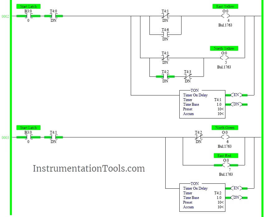
36 plc ladder diagram for traffic light
PLC Ladder logic example for beginners: Four-Way traffic ... Let's discuss the four-way traffic light control and solution based on PLC controller using ladder logic program. For this purpose, we have used Siemens PLC software TIA PORTAL V15 for developing the ladder logic program. This is one of the common examples for PLC programming beginners. FOUR-WAY TRAFFIC LIGHT CONTROL DIAGRAM Top 43 Applications of PLC in Industry and in Daily Life Jun 29, 2020 · We can see the growth of PLC in commercial control applications. With the use of PLC, applications can easily operate without or with very minimal manpower or physical hard work. Here are some basic commercial application uses PLC. Smart Traffic Control Signal System. Smart Elevator Control System. Fire Detection and Alarm System.
Best Industrial Automation with PLC Course in Hindi Off Delay Timer in Ladder Diagram 11m 10s ... Traffic Light Signal Control Logic Part - 1 ... The objective of the course is to make learners understand the generic architecture and constituent components of a Programmable Logic Controller. Knowing the make-up and functioning is desirable for industrial automation jobs.
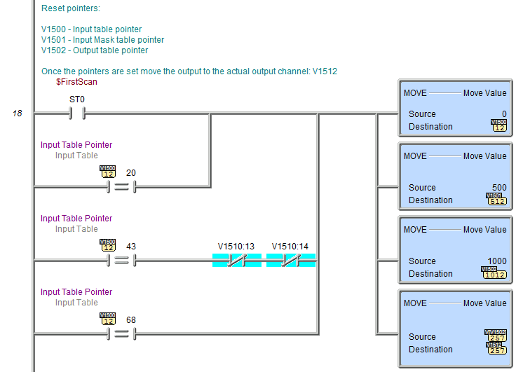
Plc ladder diagram for traffic light
AutoCAD Electrical Tutorials Webinars Tips and Tricks Electrical Computer-Aided Design Consulting for AutoCAD, AutoCAD Electrical 2017, Toolbox/WD, VIA/WD, and Promis-e. Industrial controls design specialists, including schematic, wiring diagram, bill-of-materials, wire from/to list, and panel layout, since 1988. Experienced with DIN, IEC, AS, and U.S. standards. AutoCAD Electrical training courses and training material, … Smart Traffic Control System using PLC Programming and LD ... Today, we are studying the Traffic Control System using programmable logic controller (PLC) programming based on Ladder Diagram. One of the best use of PLC programming is to control, start and stop the signals in the system. We saw different PLC software brands. For most of the project work, we use the Allen Bradley (AB) and Siemens PLC brand ... PDF Chapter 2: Basic Ladder Logic Programming Ladder Logic Diagram Example 1 Computer Aided Manufacturing TECH 4/53350 27 Task: Draw a ladder diagram that will cause the output, pilot light PL2, to be on when selector switch SS2 is closed, push button PB4 is closed and limit switch LS3 is open. (Note: no I/O addresses yet.) Thought Process
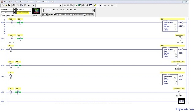
Plc ladder diagram for traffic light. traffic signal plc ladder program - YouTube hello friends, this video based on the traffic light signal program. here i used AB (allen bradly) plc software. used soft.-communication soft- RS Linx class... PLC Ladder Logic Diagram for Traffic Signal. - Instructables PLC Ladder Logic Diagram for Traffic Signal. By muneeb4889 in Circuits Software. 4,109. 2. Introduction: PLC Ladder Logic Diagram for Traffic Signal. By muneeb4889 muneeb aslam. More by the author: About: i am an electronics engineer and a short story writter for my strories visit :-muneebzargar.blogspot.in More About muneeb4889 ». Difference between DCS and PLC Systems ... Traffic Light Control using PLC Ladder Logic PLC Tutorials We most often come across a three-way traffic jam in our city. This PLC program gives the solution to control heavy traffic jams using programmable lo… PLC PROBLEM SET 2: TIMERS + COUNTERS 7. Write a ladder logic program that wili turn on a light, PL, 15 s after switch Sl has been turned on. 8. Study the on-delay timer ladder logic program in Figure 7-35, and from each of the conditions stated, determine whether the timer is reset, timing, or timed out or if the conditions stated are not possible. and DN is O. and DN is and DN is 0.
PDF Traffic Light Ladder Logic Diagram Using Sequence Traffic Light Ladder Logic Diagram Traffic Light Ladder Logic Diagram. One of the most used applications for a PLC is the traffic lights. At many schools, universities and even companies you will get the challenge to make a traffic light ladder logic diagram. The traffic light PLC program is a combination of timers Three way Traffic Light Control using PLC - Automation ... Design ladder logic for Three way traffic light control system using Programmable Logic Controller PLC programming. The traffic light is one of the classic examples in PLC ladder logic.. We can take three directions (North, South, west, and east) with three outputs (Green, Red, and Yellow) lamp as output. Traffic Light Control using PLC Ladder Logic - Inst Tools Conclusion: The above-explained 3 ways traffic light control using PLC is for example only. It may vary from real-time. We can use this example program to understand the working of timers and comparator block function in AB PLC. If you liked this article, then please subscribe to our YouTube Channel for PLC and SCADA video tutorials. FOUR WAY TRAFFIC CONTROL BY USING PLC - Technical Hub There are 5 programming languages which are used for the programming a PLC. The list is as follows: 1. Functional block diagram. 2. Ladder diagram. 3. Structure text. 4. Instruction list. 5. Sequential flow chart. Out of these five languages, Ladder diagrams is most widely used program because it is simple and easier to understand among all ...
PLC Example – Sorting Station (Shift Register) | Acc ... Oct 16, 2017 · Develop the PLC program: (Step 4 – Sorting Station Shift Register) Writing the code for the PLC example will be the next step in our program development. A quick review can be seen on our post: Buiding A PLC Program That You Can Be Proud Of (This series takes you through using discrete inputs and outputs to control traffic lights and cylinders. Traffic Light Plc Ladder Logic Diagram - Wiring Diagram ... Solved Make A Plc Ladder Diagram Program For Traffic Ligh. Plc Program To Control Traffic Lights Sanfoundry. Water Heater Ladder Diagram Siemens Plc Ladder Logic Examples. Logixsim Plclogix. Plc Program Traffic Light Youtube. 1582904514000000. Welcome to FlexSim Welcome to FlexSim. FlexSim is 3D simulation software that models, simulates, predicts, and visualizes business systems in a variety of industries: manufacturing, material handling, healthcare, warehousing, mining, logistics, and more. PLC Program for Traffic Light Control - PLC Tutorial Point Control Purpose: Enabling the traffic lights to work by Start button X0 and to stop by Stop button X1. Setting the time of red light in East-West direction as 60 sec and North-South direction with a heavier traffic as 30 sec. yellow light" in North-south direction, and vice versa. 5 sec for the crossing cars and pedestrians to pass safely.
PDF Traffic Light Plc Ladder Logic - yearbook2017.psg.fr April 22nd, 2019 - Four Way Traffic Light Ladder Diagram pdf four way junction of a traffic light the ladder logic diagram is This system will decreased the traffic congestion at traffic The best way to show how to program PLC is by The PLC diagram of the traffic light control 8075 10 Courseware Sample Lab Volt 1 / 15
Traffic Signal PLC Ladder Programming tutorial - YouTube #TrafficSignal #TrafficLight #PlcProgramming #plc #plctutorial #plcbasics #ladderlogic #ladderdiagram #programmablelogiccontrollerTutorial for Traffic Signal...
PLC Training 52 - Traffic Light Control using PLC Ladder Logic Write a PLC program for two-way traffic light control using ladder logic programming.4 Way Traffic Light Control Logichttps://instrumentationtools.com/plc-ba...
"[Help] PLC ladder diagram for traffic light (4way)" Steve Bailey - (85 posts): Feb-06-02, 09:29 AM (EST) 3. "RE: [Help] PLC ladder diagram for traffic light (4way)" You won't make any friends among the drivers on Avenue A and Boulevard B if you make them wait for a full minute for a single vehicle to enter from Causeway C or D Drive.
Traffic Light by PLC (Programmable Logic Controller ... In this video I made traffic light by PLC (Programmable Logic Controller), using the Ladder Diagram Language, the idea is how to make the timers and control ...
PLC Ladder Logic Programming Examples with detailed ... Three lights RED, YELLOW, and GREEN are connected with outputs Y0, Y1, and Y2. One switch is connected with X0 to activate and deactivate the traffic control system. Now let's have a look at the ladder logic diagram of the PLC based traffic control system. PLC based Traffic Light Control System Ladder Logic Diagram:
(Pdf) Traffic Light Signal System Based on Plc PDF | Traditional traffic light system with one fixed control mode and one single control The function conflicts with the current traffic section.... | Find, read and cite all the research you ...
Control Of Traffic Light Ladder Logic Diagram | Ladder ... Dec 1, 2019 - Control Of Traffic Light Ladder Logic Diagram. Dec 1, 2019 - Control Of Traffic Light Ladder Logic Diagram. Pinterest. Today. Explore. When autocomplete results are available use up and down arrows to review and enter to select. Touch device users, explore by touch or with swipe gestures. ... PLC Training - Introduction to PLC ...
PLC Basics | Block Diagram | Types | Applications ... May 26, 2019 · Most of the PLC programmer works on the ladder diagram programming language. It is pretty easy as compared to other PLC programming languages. How does Programmable Logic Controller Work? The most important working principle is- the PLC is operated by continuously scanning programs. Scanning happens every time per millisecond.
Top 100 PLC Projects List | PLC SCADA Projects ... Feb 18, 2019 · 92. PLC Based Automatic Traffic and Street Light Controlling System. 93. PLC Based Talking Key Pad for Blind People. 94. PLC Based Phase Sequence Indicator and Controlling System. 95. PLC Based Two Wheeler Automation With Security System. 96. PLC Based Automatic College Bell With Announcement System. 97. PLC Based Digital Gear Level …
4 Best Free PLC Software - List Of Freeware Traffic Light: This is a traffic light simulator. In this process animation, you will find a traffic light with 6 outputs. In this process animation, you will find a traffic light with 6 outputs. Enter into the programming window by pressing F5 key and design a Ladder diagram which can simulate this traffic light correctly.
SKRIPSI PLC SIEMENS S7 TRAFFIC LIGHT - academia.edu Diagram blok secara umum dilihat pada gambar 3.1, berikut : Traffic Computer PLC Light MODUL Program CPU DISPLAY Gambar 3.1 Blok Diagram Secara Umum Prinsip kerja diagram blok diatas secara umum adalah, setelah melakukan tabulasi dan data survei pada pengalamatan di lapangan (jalan raya) kemudian membuat tabel dan disusun dengan program, dimana ...
PDF Experiment 2 Traffic Light Control System for An ... - Ntua Understanding the programmable logic controller and its peripherals. Programming the PLC with the STEP 7 software. Applying the PLC to control the operation of a demand-actuated traffic light system in an intersection. Equipments: Table 1. List of Equipments 728 740 Traffic Light Crossing 730 800 PLC Basic Unit
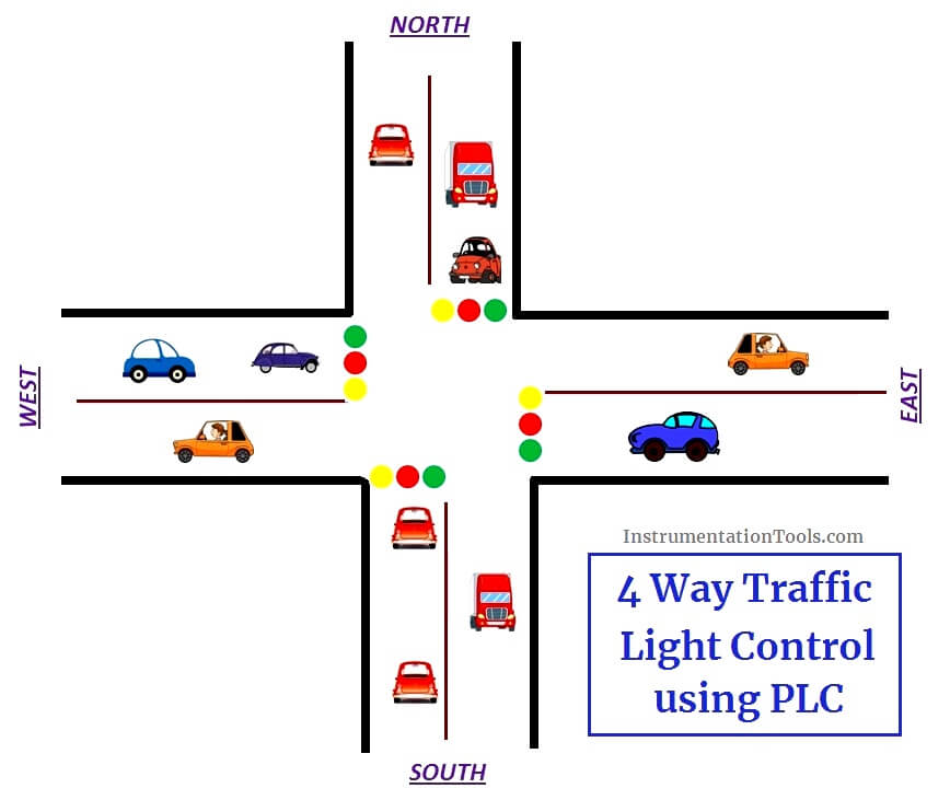
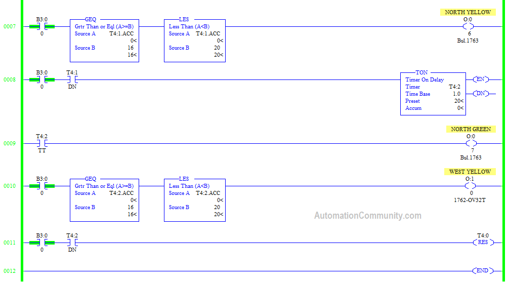
PLC based 4 Way Traffic Light Control System - Inst Tools The above explained 4 ways traffic light control using PLC is for example only. It may vary from real time. We can use this example program to understand the working of timers and Interlocking function in AB PLC. Author : Hema Sundaresan. If you liked this article, then please subscribe to our YouTube Channel for PLC and SCADA video tutorials.
PDF Traffic Light Program Logic Control Ladder Diagram Traffic Light Program Logic Control Ladder Diagram introductory plc programming wikibooks open books for. m tech it syllabus guru gobind singh indraprastha. chapter 58 safety applications ilocis org. ldmicro ladder logic for pic and avr cq cx. basic plc ladder programming examples 19. glossary of electrical terms
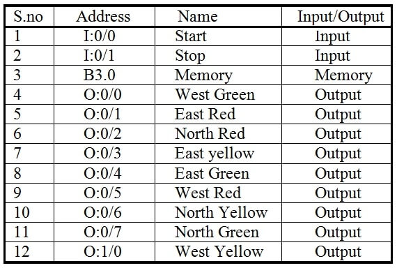
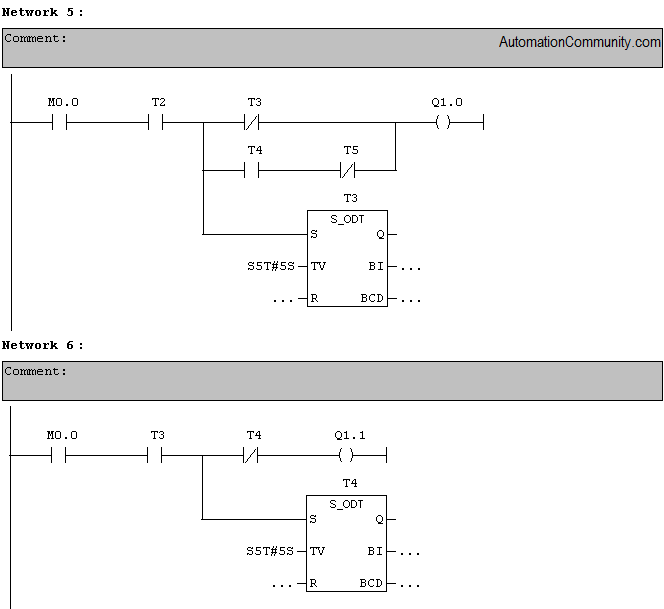
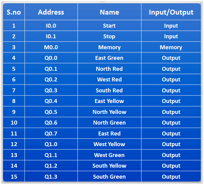
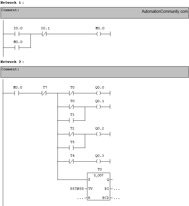
Traffic Light Control using PLC Ladder Logic Programming The traffic light is one of the classic examples in PLC ladder logic. We can take four directions (North, South, west, and east) with three output lamps (Green, Red, and Yellow). You can build your own concept for making logic for this example. Follow below tabular column - Logic for the four way traffic light List of Inputs and Outputs

PLC | How to control Traffic Lights with PLC ladder logic | Timers | Traffic lights control wirh PLC
Ladder Logic Examples and PLC Programming Examples Traffic Light Ladder Logic Diagram. One of the most used applications for a PLC is the traffic lights. At many schools, universities and even companies you will get the challenge to make a traffic light ladder logic diagram. The traffic light PLC program is a combination of timers to control which lights are turned on and for how long time.
PDF Chapter 2: Basic Ladder Logic Programming Ladder Logic Diagram Example 1 Computer Aided Manufacturing TECH 4/53350 27 Task: Draw a ladder diagram that will cause the output, pilot light PL2, to be on when selector switch SS2 is closed, push button PB4 is closed and limit switch LS3 is open. (Note: no I/O addresses yet.) Thought Process
Smart Traffic Control System using PLC Programming and LD ... Today, we are studying the Traffic Control System using programmable logic controller (PLC) programming based on Ladder Diagram. One of the best use of PLC programming is to control, start and stop the signals in the system. We saw different PLC software brands. For most of the project work, we use the Allen Bradley (AB) and Siemens PLC brand ...
AutoCAD Electrical Tutorials Webinars Tips and Tricks Electrical Computer-Aided Design Consulting for AutoCAD, AutoCAD Electrical 2017, Toolbox/WD, VIA/WD, and Promis-e. Industrial controls design specialists, including schematic, wiring diagram, bill-of-materials, wire from/to list, and panel layout, since 1988. Experienced with DIN, IEC, AS, and U.S. standards. AutoCAD Electrical training courses and training material, …

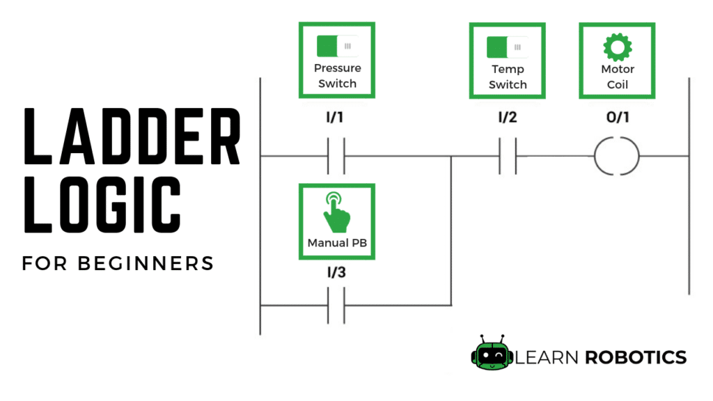

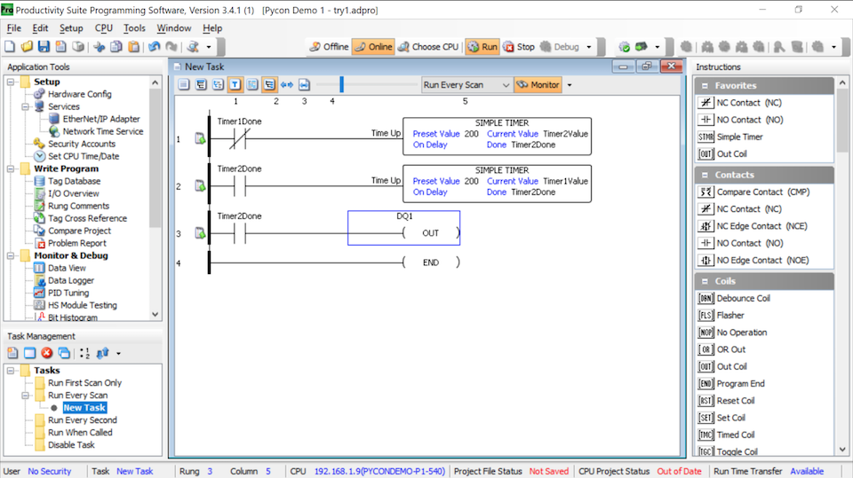


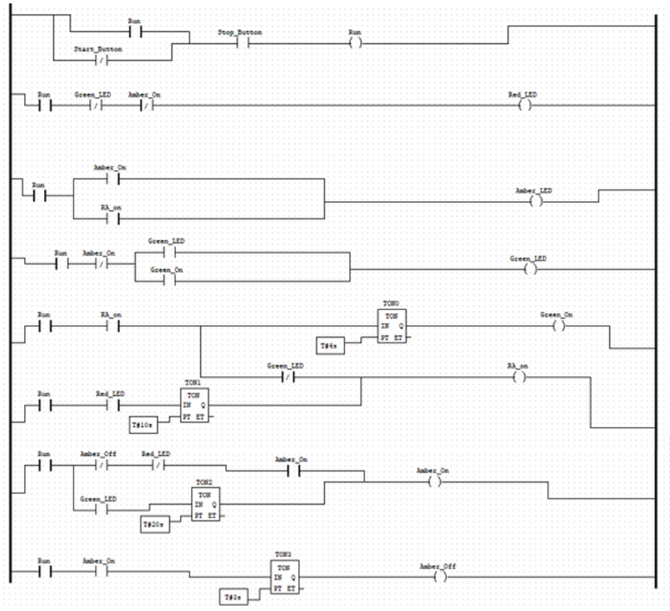










0 Response to "36 plc ladder diagram for traffic light"
Post a Comment