38 buzz coil wiring diagram
Buzz Coil Repair Operation and Service - Old Croak Buzz Coils: What to do if your coil decides to buzz off and the Buzz stops here. Ford, Jefferson, Pontiac, Kingston, Detroit and other buzzy boxes that made sparks (or were supposed to) back in the day. Buzz coils were used extensively on small engines for ignition of days gone by and by Henry Ford on the famous model T and Fordson tractor. › how-to › improve-your-fender8 easy ways to improve your Fender Stratocaster - MusicRadar Feb 07, 2022 · If you have a low to mid-price guitar there is usually some room for improvement in the electrics department; and the standard wiring and potentiometers (pots) are a good first port of call. Cheaper pots tend to have quite inconsistent resistance values. The higher your resistance, the more treble you have on tap.
Buzz Coil Wiring Diagram Database Buzz Coil Wiring Diagram from . To properly read a electrical wiring diagram, one offers to find out how the components in the program operate. For example , when a module is usually powered up and it sends out a new signal of fifty percent the voltage in addition to the technician would not know this, he'd think he has a challenge ...

Buzz coil wiring diagram
Buzz wire game diagram - the aim of this buzz wire game is Ford model t buzz coil overhaul part 1. Ford model t coil box wiring diagram. The timer roller is mounted on the end of the camshaft indexed with a pin and retained by a locking nut. Figure 5simplified diagram of integrated model t ignition components. Wiring to the coil box can be connected utes. Beginner Full instructions provided 1 hour 2,787. Buzz Coil Wiring Diagram - easywiring Buzz coil wiring diagram. The signal on pin 9 controls the reset line pin 4 of the second timer and keeps the output at pin 5 is low while pin 4 and pin 8 is low and 12 high still open. External coil wiring diagram. Joe hunt battery eliminator. Joe hunt buzz box timing buzzer. Buzz Coil Wiring Diagram - Wiring View And Schematics Diagram Buzz Coil Wiring Diagram. By Margaret Byrd | September 11, 2018. 0 Comment. The petrolist diy how to make a buzzcoil projects cenco and break joseph henry project old marine engine buzz coil ignition box circuit diagram instructions magneto for gas engines coils cheap dependable shocking truth high voltage sparks model t ford forum cut away ...
Buzz coil wiring diagram. Ignition Coil Wiring Diagram | Fuse Box And Wiring Diagram Description : Wiring Diagram For Ignition System Ignition System Wiring Diagram throughout Ignition Coil Wiring Diagram, image size 1146 X 344 px, and to view image details please click the image. Here is a picture gallery about ignition coil wiring diagram complete with the description of the image, please find the image you need. Buzz Coil Wiring Diagram - Wiring Diagram Line Buzz Coil Wiring Diagram. By Estella Vis | December 17, 2018. 0 Comment. The petrolist diy how to make a buzzcoil projects cenco and break joseph henry project old marine engine buzz coil ignition box circuit diagram instructions magneto for gas engines coils cheap dependable shocking truth high voltage sparks model t ford forum cut away ... Super Simple Ignition Coil Drivers : 7 Steps - Instructables An ignition coil (or spark coil) is nothing more than a low frequency auto-transformer with a relatively high turns ratio. The transformer typically has only a dozen or so turns on the primary but many thousands on the secondary. It is very comparable in design to the pulse transformers used in other appliances such as fence chargers, well suited for high voltage bursts. Heartwarming Permanent Capacitor Motor Diagram Buzz Coil ... The connection diagram of a permanent split capacitor motor is shown below. The two windings are displayed 90 o in space. 5 wire trailer light diagram 7 pin camper plug 5 pin relay connection diagram 6 pin trailer connector wiring diagram 6 terminal toggle switch wiring 6 wire toggle switch 7 pin electric brake wiring 7 pin round to 7 rv blade ...
PDF Simplified Diagram of Model T Ignition Components Simplified Diagram of Model T Ignition Components v2.0 By Mitch Taylor Note: Colours for the timing wires changed for the 1926-27 models; these included coloured tracers. This diagram shows the correct colours up to 1925. SPARK (WIRES) TIMING (WIRES) GROUND (BODY) GROUND (WIRES) POSITIVE (BATT) COILS (POSITIVE) COILS 6 VOLT BATTERY FIRING ORDER ... › relay-guideAutomotive Relay Guide - 12 Volt Planet The current draw of the coil is not normally shown but is typically 150-200 mA with a corresponding coil resistance of around 80-60 W. Tip: Knowing the coil resistance is useful when testing the relay for a fault with a multi-meter. A very high resistance or open circuit reading can indicate a damaged coil. Terminal numbering Ignition Box For Old Jump Spark Engines - Old Marine Engine The buzz coil is about 1½ in. long and has about 300 turns of No. 20 wire (enamel insulation). The heavy line is a 3/16 dia. steel U shape, so that I , in effect , have a horseshoe electromagnet when the current is flowing though the coil. The U shaped steel piece helps confine and concentrate the magnetic field so here is a strong pull on the ... Gibson Firebird Wiring Diagram - easywiring Maxresdefault On Les Paul 50s Wiring Diagram . Variety of gibson firebird wiring diagram. Gibson firebird wiring diagram.Pickup wiring diagram gibson les paul jr gibson p90 pickup wiring. 50 s wiring diagram and easy to read step by step installation instructions. 60s firebird v wiring diagram i have a klein in my fb i and in the middle of my fbvii.
Buzz Coil Wiring Diagram For Hit And Miss - schematron.org Buzz Coil Wiring Diagram For Hit And Miss. 12.01.2019 12.01.2019 0 Comments on Buzz Coil Wiring Diagram For Hit And Miss. Schematic for the Ford Model T buzz coil. Could someone tell me how to check a Ford Model T coil before I go through all the trouble of soldering some clips. PDF Vol 2, Issue 1 2009 Jack Craib had posted a digital picture of a diagram that detailed a proven method of wiring up a buzz coil and battery that should be capable of providing an operational ignition system for any single- cylinder rowboat motor, and here is a reproduction of that sketch to use for reference. issrmaterecclesiae.itissrmaterecclesiae.it 1) It is 10/2 UF cable ran through PVC conduit into the trench until the trench depth reaches 24 inches on both sides (shed and house) of the run. This type of wiring diagram shows, as closely as possible, the actual location of each component in a circuit, including the control circuit and the power circuit. Mazda B2200 Ignition Wiring Diagram - Diagram Diagram buzz coil wiring full 1989 mazda b2200 no fire to distributor ignition wrong street source gy6 wire systems a short course injector pulse electrical problem 4 alternator wires help switch on ls1 pack pinout. Mazda B2200 Wiring Diagram 1991 Mazda B2600I Horn Wiring Diagram B2600I Credit.
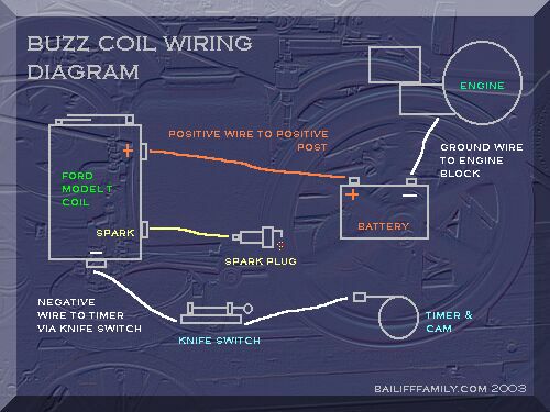
Buzz coil hook up | Smokstak® Antique Engine Community To test the coil, - FIRST rig a wire from the spark plug terminal to about 1/4" of the other top terminal. This will act as a safety spark gap. If you do not use a safety gap, the high voltage could arc inside the coil, ruining the insulation. ... Buzz Coil Diagram . Attachments. buzzmap.jpg. 79.9 KB · Views: 388 TheToolman Registered. Age 74 ...
en.wikipedia.org › wiki › Transformer_typesTransformer types - Wikipedia A variety of types of electrical transformer are made for different purposes. Despite their design differences, the various types employ the same basic principle as discovered in 1831 by Michael Faraday, and share several key functional parts.
PDF msd ignition wiring diagram - technicalmanual.buzz Free Wiring Diagram. Collection of msd ignition 6al wiring diagram. A wiring diagram is a simplified conventional pictorial depiction of an electric circuit. It shows the elements of the circuit as streamlined shapes, and the power as well as signal connections in between the gadgets.
Building Your Own Ignition System - Gas Engine Magazine ... If you desire to build a buzz coil spark ignition system, then continue on. Note: A condenser from any automotive or small gas engine ignition system will work in the systems shown in the Image Gallery. Direction of hookup is not critical. For a buzz coil ignition system, start with a mounting board about 1/2″ x 3-1/2″ x 1/8″ to 1/4″ thick.
IOT Wiring Diagram - Page 201 of 217 - Find us for search ... Buzz Coil Wiring Diagram The petrolist diy how to make a buzzcoil projects old marine engine buzz coil magneto ignition for gas engines coils cenco and break joseph henry project cheap dependable dew wiring diagram shocking truth high voltage sparks tremble answer mystery device standing well back micro v3 model t ford igntion restoration ...
› emg-faqEMG Pickups / FAQ / Electric Guitar Pickups, Bass Guitar ... To get a split coil sound out of a humbucker we recommend the EMG 89, which contains both a humbucker and single-coil in one pickup switched via an included push/pull pot. The EMG PI2 Phase Inverter actively inverts the phase of an EMG pickup giving you a true out-of-phase effect, controllable by a switch.
Model T Buzz Coil Wiring Diagram File Name : Model T Buzz Coil Wiring Diagram. File Size : 46391 Kb. We all know that reading Model T Buzz Coil Wiring Diagram is useful, because we are able to get enough detailed information online from the reading materials. Technology has developed, and reading Model T Buzz Coil Wiring Diagram books might be far more convenient and much easier.
silverhookstudiosinc.us › ebike-light-wiringEbike light wiring - silverhookstudiosinc.us Mar 28, 2022 · This product is sold for AS-IS and does not come with a wiring diagram or instructions. The BLACK wire is the power supply line to the brake control. 99. Bosch Active Line gen. 13 5% off 5% off previous price £11. Quietkat produce solid built ebikes for hunting with top components. com/x/fqj0WTIn this Assortment of ebike wiring diagram.
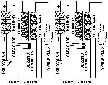
A Cheap Dependable Buzz Coil - Old Marine Engine A wire is jumped terminal 86 to 87a. A wire is connected from terminal 30 to the battery positive. The condensor can be screwed onto the coil terminal, this mounts it and makes a connection, a wire is then run run to terminal 30. If you look at the diagram you will see that this is giving you a condensor across the relay points.
How to make a buzz coil Part 1 - YouTube Check out our new channel "HisLifeHerWay'This is how to make a spark plug ignition buzz coil for your custom projects like pulse jets, hho, turbo jets, firew...
Buzz Coil Wiring | Antique Outboard Motor Club,Inc Replies: 516. Topics: 48. November 30, 2018 at 1:56 pm #157638. I assume you have a standard Model T buzz coil, with one power terminal on top, one on the bottom, and the spark plug terminal in the middle. Run one battery terminal (-) to the ground of the motor. Run the other battery terminal (+) to the top terminal of the coil.
BUZZ COIL HOW TO HOOK UP TO HIT MISS ENGINE - YouTube sometimes if not working just dusty from sitting spray with electrical cleaner or just blow it out good.but sometimes you may have to take apat the top and c...
Buzz Coil - Tractor Parts 14 Motor Engine Spark Ft Orange Gas 5 Hit Coil Wire Buzz Primary Miss Ga 5 Ft 14 . $10.50. Lot Of 3 High Tension Buzz Coil For Hit Miss Gas Engine Parts Only Lot Of. Of Tension Parts Only Engine High Hit For Buzz 3 Gas Miss Coil Lot Lot Of 3 . $49.99. Antique Mesco Buzz Coil Antique Mesco.
Instructions - Hunt Magnetos Cap Wiring Diagram: View. Installation And Timing: View. Internal Coil Wiring Diagram: View. External Coil Wiring Diagram: View. Advance Kit Installation: View. Motorcycle Magnetos. Early Model Harley '74 Magneto Installation (#1274) ... Joe Hunt "Buzz Box" Timing Buzzer: View. Joe Hunt Battery Eliminator: View. Joe Hunt Universal Tach Converter:
The Shocking Truth: How To Make High-Voltage Sparks ... How to Build It: Spark Plug Doing Its Thing. Putting this Buzz Coil together is as simple as following the wiring schematic. If you're using a socket for the relay, make the connections to the ...
› wiki › indexWilliams WPC - PinWiki Mar 25, 2022 · 4 Recommended Documentation 4.1 Manuals & Schematics. Schematics for each game are essential in tracing down connections to lamps, switches, and solenoids. The owner's game manual is a handy resource to have for general game operation, game settings & diagnostics, switch & lamp matrices, fuse lists, circuit boards and parts, playfield assemblies, some basic schematics, and wiring diagrams.
Model T Schematic and Wiring Diagrams MODEL T SCHEMATIC AND WIRING DIAGRAMS December 2, 2018 Version 1.1 By Bob Cascisa I created four schematic diagrams for the Model T electrical system. A schematic diagram is a graphical representation of electrical circuits and typically does not show installation ... Coil ignition system only. 1915 - 1916 With Magneto headlights and horn. ...
Buzz Coil Wiring Diagram - Wiring View And Schematics Diagram Buzz Coil Wiring Diagram. By Margaret Byrd | September 11, 2018. 0 Comment. The petrolist diy how to make a buzzcoil projects cenco and break joseph henry project old marine engine buzz coil ignition box circuit diagram instructions magneto for gas engines coils cheap dependable shocking truth high voltage sparks model t ford forum cut away ...
Buzz Coil Wiring Diagram - easywiring Buzz coil wiring diagram. The signal on pin 9 controls the reset line pin 4 of the second timer and keeps the output at pin 5 is low while pin 4 and pin 8 is low and 12 high still open. External coil wiring diagram. Joe hunt battery eliminator. Joe hunt buzz box timing buzzer.
Buzz wire game diagram - the aim of this buzz wire game is Ford model t buzz coil overhaul part 1. Ford model t coil box wiring diagram. The timer roller is mounted on the end of the camshaft indexed with a pin and retained by a locking nut. Figure 5simplified diagram of integrated model t ignition components. Wiring to the coil box can be connected utes. Beginner Full instructions provided 1 hour 2,787.


0 Response to "38 buzz coil wiring diagram"
Post a Comment