39 primary secondary piping diagram
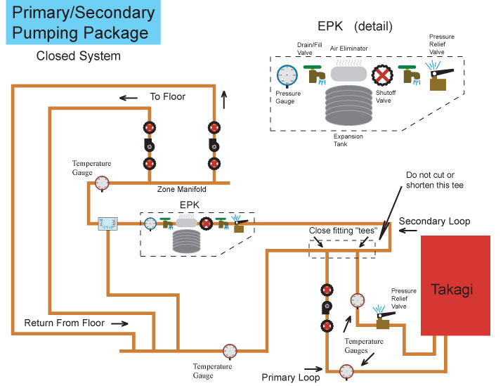
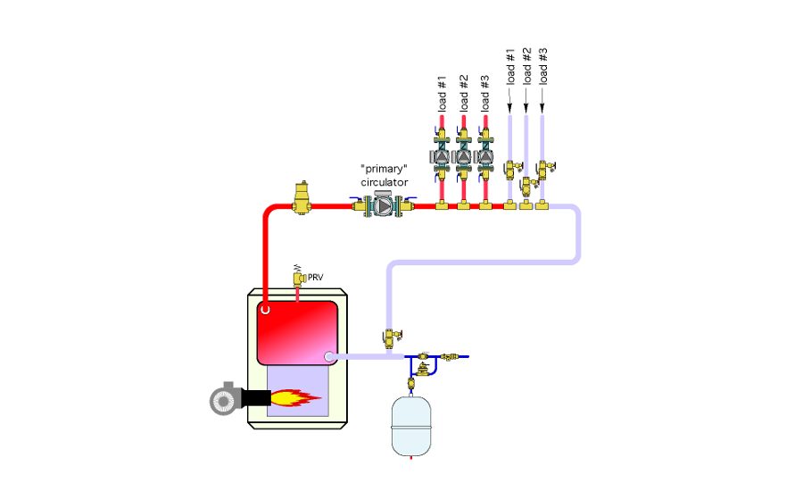
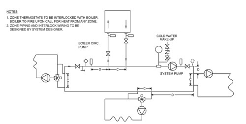
PDF Condensing Boilers in Primary Variable Flow Piping Systems Traditional Primary/Secondary System • Decouples or "hydraulically separates" the primary (boiler) and secondary (system) loops - Closely spaced tees or a mixing manifold • Prevents flow in one circuit from interfering with another - Example: As zone valves open, close, or modulate, and as system pumps vary speed, the Hydronic System Primary-Secondary Rules-Decoupling Systems The piping common to both the secondary and primary loops are the two tees and the common piping shown above. Rule "1" tells us to keep that common pressure drop very low. The reason being if there is nothing to stop it, the pressure drop in that pipe will cause a flow in the secondary circuit, even if the secondary pump is off.
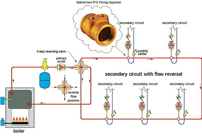
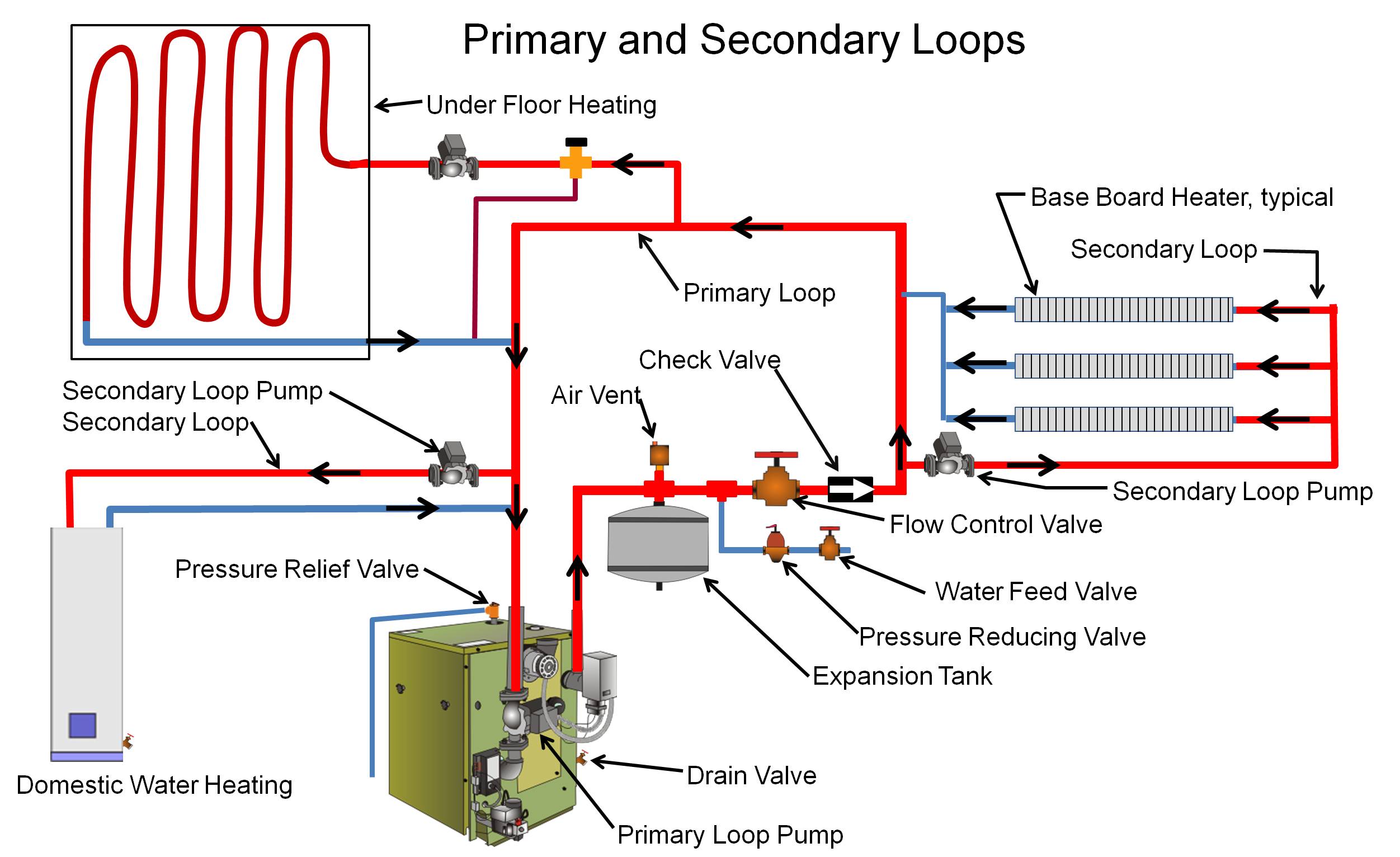
Primary/Secondary plumbing | | DIY Radiant Floor Heating ... Primary/Secondary plumbing has been used for years in commercial and residential heating and cooling applications. In a radiant heating application, a properly sized pump on the Primary Loop triggers the on-demand heater whenever any zone calls for heat. This creates a circulating loop of hot water between the heater and a pair of closely spaced tees that intersect with a Secondary Loop.
Primary secondary piping diagram
Piping Schematics Primary Secondary: PDF : Primary Secondary Tertiary: PDF : Variable Primary: PDF : Zone: PDF : Chilled Water Buffer Tank: PDF : Cooling Tower Schematics : Multiple Cell: PDF: Multiple Cell Concrete Basin: PDF: Field Erected: PDF: Filtration: PDF : Hot Water Schematics : Condensing Gas Boiler: PDF: Non-Condensing Gas Boiler: PDF : Plumbing Schematics : Condensing Gas Water Heating: PDF PDF Beyond Primary / Secondary Piping - Caleffi Flow in the primary loop is 50 gpm with a corresponding head loss of 15 feet (6.35 psi pressure drop). Assume a wet rotor circulator with wire-to-water efficiency of 25 is used as the primary circulator. The input wattage to the circulator can be estimated as follows: W= 0.4344×f×∆P 0.25 = 0.4344×50×6.35 0.25 =552watts PDF Lochinvar :: High efficiency Water Heaters, Boilers and ... Lochinvar :: High efficiency Water Heaters, Boilers and ...
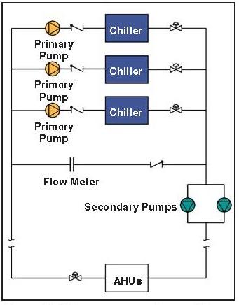
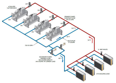
Primary secondary piping diagram. PDF Hydronics - Step By Step - TACO - HVAC In a primary-secondary piping arrangement, which water temperatures should be taken off the primary first? Always take the highest water temp off the primary first. The primary temp will drop as more secondaries are taken off. 2-Way Injection • How does 2-way valve injection work? 2-way Primary/Secondary Piping: Back By Popular Demand - PM Engineer Primary/ secondary piping is a versatile piping method that's increasingly being used as the backbone of modern multi-load/multi-temperature hydronic systems. The concept of primary/secondary (P/S) piping has been around since the mid 1950s. Until the last decade, it was used mostly for larger commercial heating and chilled water cooling systems. PDF I. Piping Diagrams I. PIPING DIAGRAMS Figure 6 . 23 LP- 276 REV. 3.28.14 Figure 7 NOTES: 1. This drawing is meant to demonstrate system piping concept only. Installer is responsible for all equipment and detailing required by local codes. 2. Boiler circulator(s) must be rated for open loop applications. Do not use cast-iron circulators. Making Them Work: Primary-Secondary Chilled Water Systems Dedicated primary pumps (each pump is dedicated to a single chiller by direct piping [ Figure 2) are used, in part, because of the simple nature of the chiller plant operation. It is easy to understand that because Pump 1 is piped directly to Chiller 1, whenever that chiller is operating its dedicated pump should be operating.
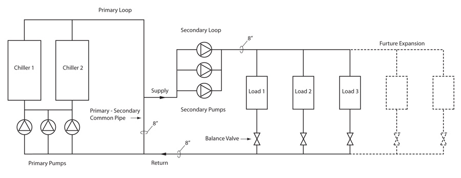
Understanding primary-secondary pumping If one or more of your secondary zones are going to serve a radiant heat zone, use a two-, three-, or four-way valve to mix the water returning from your zone into the hot supply water from the primary circuit. Pipe your secondary circulator on the radiation side of the two-, three-, or four-way valve. Primary Secondary Pumping - The Tee Law - YouTube Primary Secondary Pumping - The Tee Law Piping diagrams - Raypak Raypak Pool & Spa, Residential and Commercial Hydronic Products - Understanding Primary Secondary Pumping Part 1: Behold the ... At the bottom we see the primary piping (sometimes referred to as the "production piping") and we see the secondary loop and cooling circuit that is connected to the primary piping at either end by two tees. These two tees (shown in green) represent what is often referred to as the common pipe. Figure 2
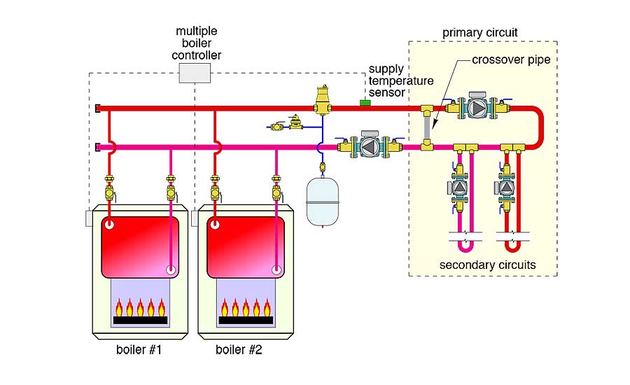
PDF Near Boiler Piping - Lochinvar, LLC multiple boiler - primary/secondary piping crest . from system relief valve hot water generator water generator circulator boiler drain (typical) boiler pump (typical) ball valve (typical) air seperator drain port (typical) system circulator to system make up water back flow preventer pressure reducing valve pressure Boiler Heating Primary Loop / Boiler Secondary Loops Primary Loop Piping is commonly used in boiler heating systems that run needing multiple temperatures or contstant temperature at the hydronic boiler is required. Primary Loop Piping allows non condensing boilers to maintain a heat level in the boiler high enough to allow the boiler to run at its most efficient state. Primary Secondary Tertiary System in Hydronic Heating In our example above the purple piping is normally called the "Primary System". This is the system with the boilers and boiler circulating pumps. The red piping is normally called the "Secondary System". The blue piping is normally called the "Tertiary System" This can be a coil with pump or other terminal out in the system. PDF BASIC HYDRONIC SYSTEM DESIGN - ctashrae.org IN-LINE 20 - 375 10 - 75 ¼ - 3 1760, 3500 END SUCTION 40 - 4,000 10 - 400⅓- 200 1160, 1760, 3500 VERTICAL IN-LINE 40 - 12,000 10 - 400 ¼ - 600 1160, 1760, 3500 SPLIT CASE 100 - 18,000 20 - 500 3 - 1,500 1160, 1760, 3500 VERTICAL TURBINE 20 - 6,000 10 - 150 ½ - 150 1160, 1760. TYPICAL CAPACITIES.
Piping Diagram - Cemline Piping Diagram Technical Resources Product Drawings Piping Diagram Technical Papers 3D-Drawings Spec Sheets CEMLINE® has made a series of typical piping arrangements for the Model Series: SEH, SSH, SWH, and USG. These drawings are in .DWG format or Adobe®Acrobat® (PDF) format. The Acrobat Reader is available free from Adobe.
PDF Modern HydronicSystem Designs for Condensing Boilers Primary/Secondary Piping For Condensing Boilers (Multiple) Monday, December 01, 2014 Modern Hydronic Designs For Condensing Boilers 10 Equal Flow Distribution • Boiler GPM = System GPM • Very little mixing • Equal system/boiler supply and return temperatures • This is situation is idealfor a condensing boiler • Very difficult to achieve in practice
PDF Primary Secondary Pumping Application Manual Figure 15 - TEE "A" FLOW; PRIMARY FLOW = SECONDARY FLOW The over-all circuit can be shown as illustrated in Figure 16. Figure 16 - COMPLETE CIRCUIT FLOW; PRIMARY FLOW = SECONDARY FLOW When the primary flow rate is set equal to the secondary there will be no flow rate in the common piping. Secondary
Primary Secondary Chilled Water Piping Diagram Figure 2 shows a simplified schematic of a primary/secondary piping system. At the bottom we see the primary piping (sometimes referred to as. This example will discuss the basics of primary/secondary pumping systems and some of the The chilled water from the supply side of the primary chilled water loop is passes The simple line diagram for the system is shown in Figure.
Hydronic Heating Boilers - Water Heaters Hydronic Heating Boilers Description Series Piping Diagram PDF Piping Diagram DWG Genesis® One Boiler Primary, Secondary Hydronic Heating System GB 300 2500 AOSHG61080 AOSHG61080 Genesis® Two Boilers Primary, Secondary Hydronic Heating System GB 300 2500 AOSHG61081 AOSHG61081 Genesis® Three Boilers
PDF BASIC HYDRONIC SYSTEM DESIGN - ctashrae.org DECOUPLERS Closely Spaced Tees Buffer TankHydraulic Separator (depends) DECOUPLER Head = 0' PRIMARY FLOW TERMINAL UNIT Head = 10' - 20' CLOSELY SPACED TEES Distance Between Tees as Short as Possible (Tee to Tee). Pressure Drop Between Tees Will Determine Flow to Terminal Unit WATER ALWAYS FOLLOWS PATH OF LEAST RESISTANCE 5 HYDRAULIC SEPARATORS
Primary secondary piping for boilers - Hearth.com Forums Home Primary secondary systems need circs to work properly. you could add zone valves down stream of the circs for additional zones. There are a lot of small circs on the market, as well as 3 speed to dial in an almost exact flow rate at very small wire to water consumptions. we may even see a 1 watt pump on the market soon. laing also builds some very small flow circs.
Understanding Primary Secondary Pumping Part 6: 5 Ways to ... Primary-Secondary-Tertiary Hybrid. Primary-secondary-tertiary designs may also be hybridized, meaning you don't have to put a tertiary loop on every zone. Rather, you can isolate a high head loss zone with a tertiary pump while continuing to efficiently serve nearby zones with the secondary pumps. Figure 4 shows a primary-secondary-tertiary hybrid design.
Primary Secondary Chilled Water Piping Diagram Primary Secondary Chilled Water Piping Diagram 18.08.2018 7 Comments Primary-Secondary pumping has grown in stature since its concep- tion by Bell and the radiation circuit into the main and is installed in piping which is common to .. Most chilled water systems are designed with a constant supply water.
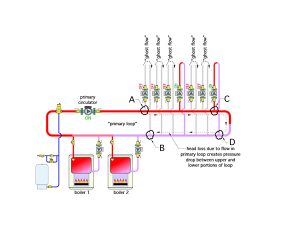
Piping layouts to avoid in hydronic systems - HPAC Magazine This piping layout eliminates the "ghost flow" and possible recirculation issues previously described. It also provides equal supply temperatures to each of the load circuits. It does away with the primary loop circulator, and perhaps most importantly, it eliminates the operating cost of a primary loop circulator over the life of the system.
Boiler Piping Diagram For Radiant Heat In a radiant heating application, a properly sized pump on the Primary Loop triggers the Unless, as stated above, a specific boiler manufacturer requires Primary/Secondary The schematic below illustrates the piping configuration when. Images of Piping Diagram For Radiant Floor Heat.
PDF Lochinvar :: High efficiency Water Heaters, Boilers and ... Lochinvar :: High efficiency Water Heaters, Boilers and ...
PDF Beyond Primary / Secondary Piping - Caleffi Flow in the primary loop is 50 gpm with a corresponding head loss of 15 feet (6.35 psi pressure drop). Assume a wet rotor circulator with wire-to-water efficiency of 25 is used as the primary circulator. The input wattage to the circulator can be estimated as follows: W= 0.4344×f×∆P 0.25 = 0.4344×50×6.35 0.25 =552watts
Piping Schematics Primary Secondary: PDF : Primary Secondary Tertiary: PDF : Variable Primary: PDF : Zone: PDF : Chilled Water Buffer Tank: PDF : Cooling Tower Schematics : Multiple Cell: PDF: Multiple Cell Concrete Basin: PDF: Field Erected: PDF: Filtration: PDF : Hot Water Schematics : Condensing Gas Boiler: PDF: Non-Condensing Gas Boiler: PDF : Plumbing Schematics : Condensing Gas Water Heating: PDF













0 Response to "39 primary secondary piping diagram"
Post a Comment