35 5 wire door lock diagram
Title: CHRYSLER 3-5 WIRE DOOR LOCKS AL Author: Administrator Created Date: 8/11/2004 11:13:17 AM Dec 23, 2018 · December 23, 2018. 5 Wire Actuator Diagram . Actuator spring door actuator wiring 5 wire central locking actuator wiring diagram simple servo type direct acting diagrm pneumatic cylinder diagram pneumatic actuator diagram double acting actuator cutaway diagram 5 wire door lock actuator diagram 17.vancouvervisions.com.
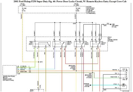
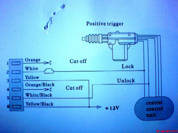
When connecting to an ALARM SYSTEM, use all 4 DOOR TRIGGER wires and DIODE ISOLATE. to connect, See DIAGRAM NOTE #6: the PCM (Powertrain Control Module) is located on the PASSENGER SIDE firewall, the DIESEL tach wire is a GRAY/BLACK at the ECM (Electronic Control Module) on the lower drivers side of the engine, 60 pin plug, pin 24.

5 wire door lock diagram
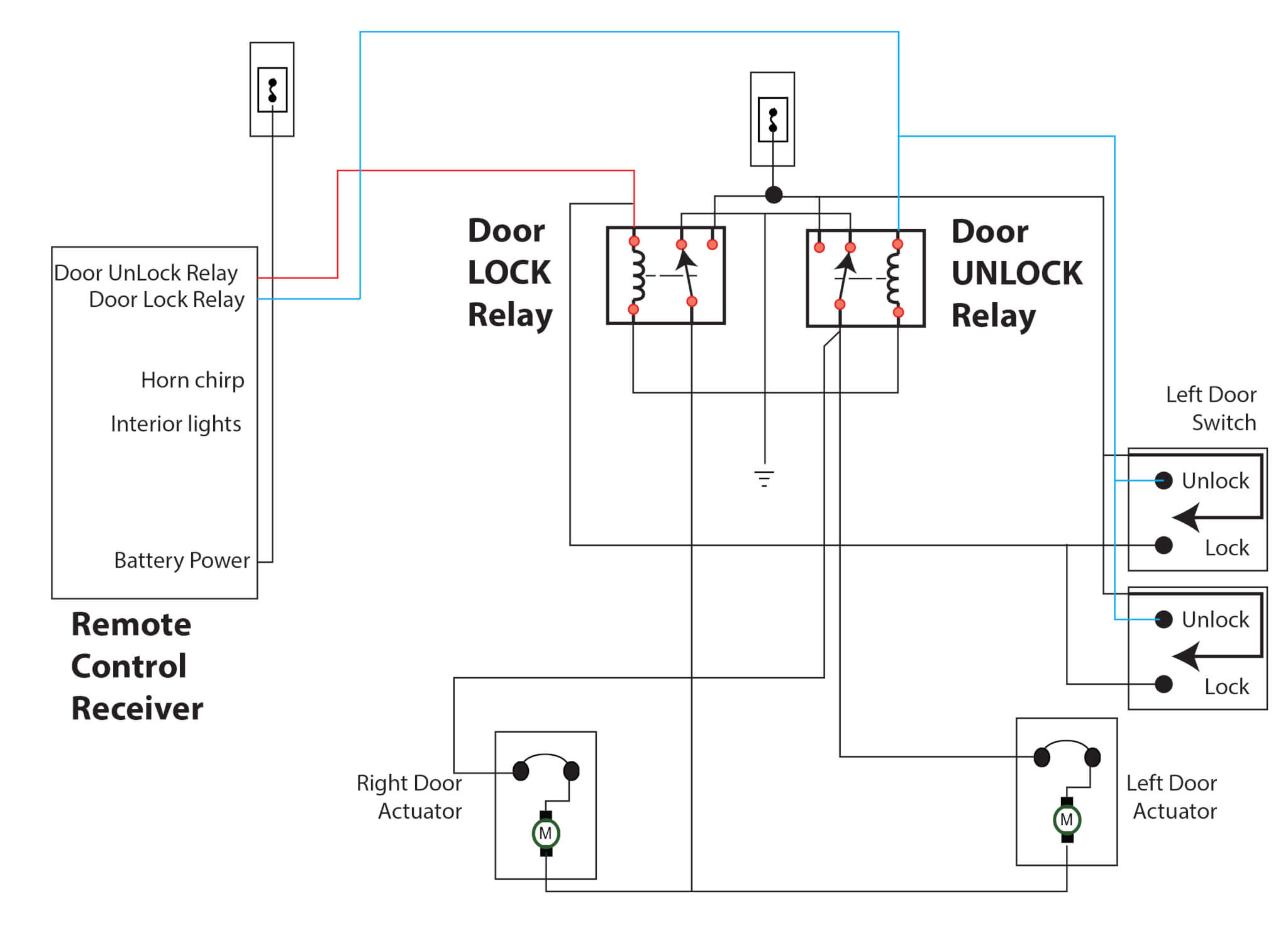
Wiring Diagrams 1. Understanding Diagrams Page U-1 Lighting Systems 1. Headlights Page L-1 2. Turnsignals & Hazard Page L-2 3. Stop Lights Page L-3 4. Backup / Horn Page L-4 Accessories Systems 1. Power Windows Page A-1 2. Power Mirrors Page A-2 3. Door Locks Page A-3 4. Clock & Cig Lighter Page A-4 5. Front Wiper & Washer Page A-5 6. Blower ... Door Locks - 5 Wire Alternating 12 Volts Positive (Type C) Relay Wiring Diagram. How to Wire Automotive SPDT Relays. Door Locks - 5 Wire Alternating 12 Volts Positive (Type C). The switch, when moved in either direction, applies both power and ground directly to motor legs without the use of any relays. Except, at the switch in this case, both motor legs rest at ground . POWER DOOR LOCK (5-wire reverse polarity) LT. BLUE Harness Coming Into Vehicle From Driver's Door Or Harness In Driver's Kick Panel POWER DOOR UNLOCK (5-wire reverse polarity) BLACK/WHITE Harness Coming Into Vehicle From Driver's Door Or Harness In Driver's Kick Panel PARKING LIGHTS (+) BROWN At Light Switch Or Driver's Kick Panel
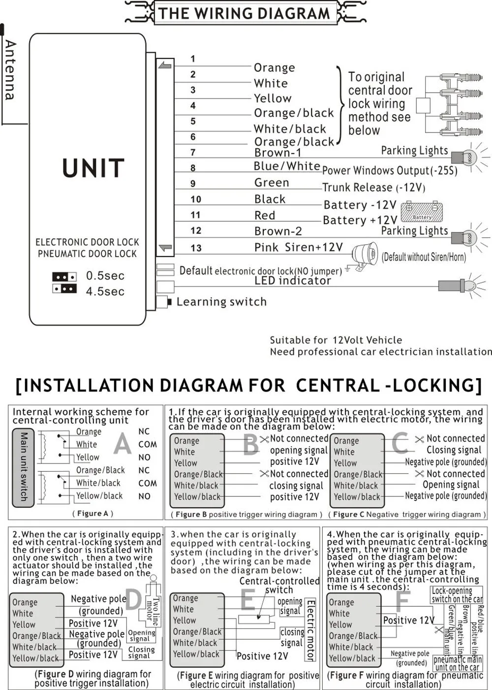
5 wire door lock diagram. Dec 27, 2020 - 5 Wire Door Lock Actuator Wiring Diagram Wire Center Best Of Power From the thousands of photographs on the net about door lock actuator wiring diagram, we all choices the very best collections with best resolution just for you all, and this photographs is actually considered one of photos collections in this very best pictures gallery concerning Door Lock Actuator Wiring Diagram.I hope you will as it. This kind of impression (Aftermarket Door Lock Actuator ... There are 5-wire motors and 2-wire motors. The 5-wire version is used indoors that have a key-lock. There are 2 connections for the motor itself and 3 connections for the sensor part (an 'open' and a 'close' contact). These sensors determine whether the door is to be unlocked or locked. If there is no key lock in the door, these sensors ... When the switch is closed, the green/white wire sends a signal to terminal 6 of the PSE, either from Green/red, or ground (brown). The PSE either sends vacuum or pressure to the door lock actuator. The green/red gets power from F4f11, so fuse 11 in the rear fuse box. Other wires at the switch are only for lighting.
12v Central Lock Universal Remote For Keyless Entry P N 900 550 Manualzz. Wiring up a keyless remote on 60 central locking for honda civic type r door lock system kit entry install car alarm with installing how vehicle electronics gps alarms systems auto 4 power bimmerforums the ultimate bmw forum do i universal e34 website vw transporter t5 12v ing installation guide actuator 5 wire relay ... The following common wiring diagrams are available: Standalone with access control and Magnetic Lock · Wireless Multi-Technology Reader - GCK> Magnetic Lock Setup Guide Diagram from the manual that shows where to connect wires. Larger diagram In this example, the manual labeled the blue wire leaving the 6-pin connector as the negative ... 96 Chevy Power Door Lock Wiring Wiring Diagram. Repair Guides Power Door Locks 2002 Power Door Lock System. Electic Gm Wiring Harness Diagram Door Locks Wiring Diagram Toolbox. Smart Lock Wiring Diagram Wiring Diagram Centre. Door Relay Lock Door Lock Relay Module Sc 1 St Sonic Electronix. powering a lock, the minimum inductive load (lock) power wire guage shall be determined using the sdc wire guage chart or another voltage drop estimation tool. all wiring (single or multi- conductor) shall be color coded without splices. a minimum of two spare conductors is recommended. 6. voltage may not be specified on these wire diagrams. verify
power door locks wikipedia. how to wire up a 5 wire door lock actuator relay from start to finish very easy how to wire up relays and install locks on vehicles that don t come with power door locks or does not offer any analog inputs to tap you outputs from you alarm remote start on to door 5 wire 5 wire actuator wiring diagram for wiring diagram database 5 wire actuator wiring diagram for 5 ... Nov 28, 2020 · Central Locking 5 Wire Door Lock Actuator Wiring Diagram Database. Fixing electrical wiring, even more than some other house project is focused on protection. Install an electrical outlet properly and it's since safe as it can be; set it up improperly and it's potentially deadly. That's why there are several guidelines surrounding electrical electrical wiring and installations. system. Make sure to mark which wire is lock and unlock. "Type B" Door Lock Test (Most Imports, some newer Fords) Probe both door lock wires going to the door lock switch these wires are usually located in the driver's kick panel. Attach one end of your test light to +12V using the vehicle's door lock controls activate Mar 26, 2019 · 5 Wire Door Lock Actuator Wiring Diagram. Wiring Diagram March 26, 2019 07:27. 5 Wire Door Lock Actuator Wiring Diagram Actuator Wiring Circuit Manual E Book. 5 Wire Door Lock Actuator Wiring Diagram – wiring diagram is a simplified pleasing pictorial representation of an electrical circuit. It shows the components of the circuit as simplified shapes, and the power and signal associates in the company of the devices.

Anyone Know How The Power Door Lock Actuators Work Pelican Parts Forums
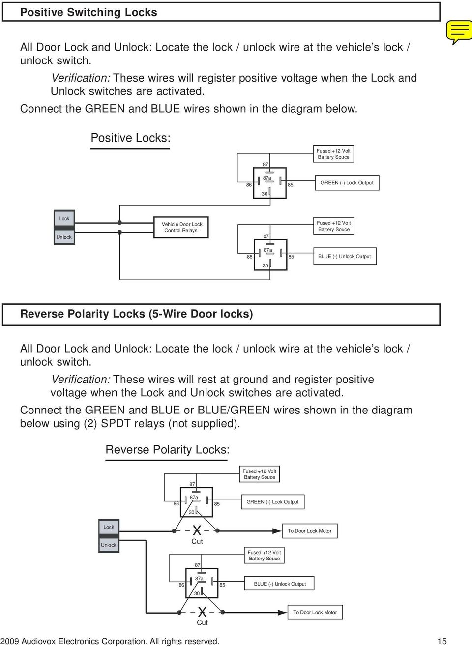
May 04, 2020 · Door Locks - 5 Wire Alternating 12 Volts Positive (Type C) Relay Wiring Diagram. The switch, when moved in either direction, applies both power and ground directly to motor legs without the use of any relays. Except, at the switch in this case, both motor legs rest at ground . Therefore it is only necessary to change the polarity of one motor leg to lock or unlock the vehicle.
Door Locks Actuators Reverse Polarity Positive Switch Trigger Type D Relay Wiring Diagram
Diagram-5-Wire-Door-Lock-Actuator-Wiring-And-Wellreadmerhwellreadme - 5 Wire Motor Wiring Diagram. The diagram offers visual representation of a electric structure. On the other hand, this diagram is a simplified variant of the arrangement. It makes the process of building circuit easier.

3 Wire Positive Door Locks Relay Diagram Door Lock System Car Door Lock Door Locks
5 Wire Alternating 12 Volts Positive Door Locks Relay Diagram (Type C) 5 Wire Alternating 12 Volts Positive Door Locks Like the 4 wire configuration , the switch, when moved in either direction, applies both power and ground directly to motor legs without the use of any relays.
Power Door Locks Wikipedia
Wiring Diagrams 1. Understanding Diagrams Page U-1 Lighting Systems 1. Headlights Page L-1 2. Turnsignals & Hazard Page L-2 3. Stop Lights Page L-3 4. Automatic Light Turn-off Page L-4 5. Daytime Running Lights Page L-5 Accessories Systems 1. Rear Window Defogger Page A-1 2. Power Windows Page A-2 3. Power Mirrors Page A-3 4. Door Locks Page A ...
Bmw Gm5 Wiring Connections
Power Door Locks & Wiring DiagramAmazon Printed Bookshttps://www.createspace.com/3623931Amazon Kindle Editionhttp://www.amazon.com/Automotive-Electronic-Diag...
Security And Remote Start Installation Guide For Models Ca 6150 Ca Pdf Free Download
Here is an easy 5 wire setup for anyone to use in any vehicle without the use of any relays
Power Door Lock Wiring Diagram Both Sides Quit At The Same Time
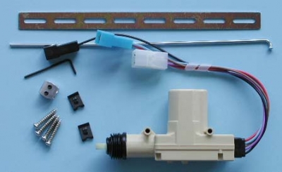
WIRING DIAGRAMS 1 2 TECH SUPPORT HOTLINE: 503.693.1918 ... Repeat steps 1-10 for each door. WIRING 1. Run all the wires to the location of the door lock module. Be sure to ... factory door lock rod using the screws given (Figure 2). You can mount the actuator directly to the door, or use the bracket to cross a part of the ...
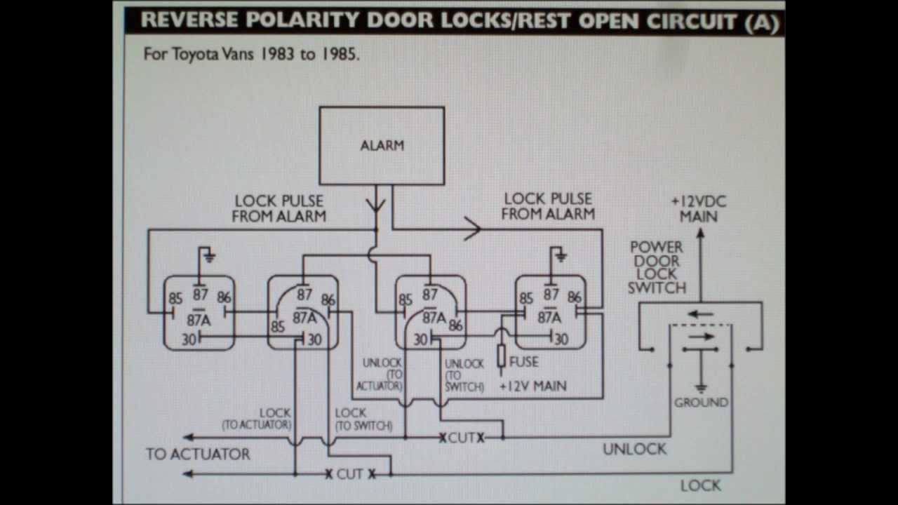
How To Wire 5 Wire Reversing Polarity Door Locks In Early Toyota And Ford Youtube
3. Cut the drivers door lock wire. This wire will have 12 volts when lock button is pushed. 4. Connect the ORANGE/BLUE wire to the switche's side of the lock wire. 5. Connect the BLUE/WHITE wire to the motor's side of the lock wire. 6. Cut the drivers unlock wire. This wire will have 12 volts when unlock button is pushed. 7.
Set Kit Remot Kunci Otomatis Mobil Sistem Alarm Pengunci Pintu Sistem Penguncian Kendaraan Tanpa Kunci Dengan Pengendali Jarak Jauh M616 8217 Buy Central Mengunci Entri Tanpa Kunci Remote Mobil Keamanan Alarm 4
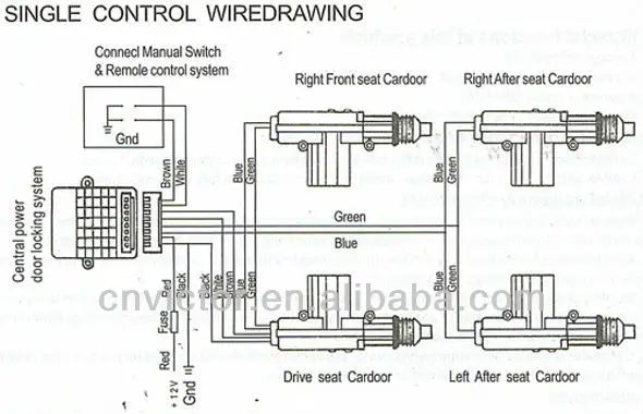
if you are doing a conversion from non power to power locks use the 5 wire to control the other locks. green lock, blue unlock. wire up the relays like your diagram and run it to the blue and green wire on the actuator. the actuator on the passenger door cut off the white brown and black wire and on the driver door ground the black wire and tie in the white and brown wire on the blue and green ...
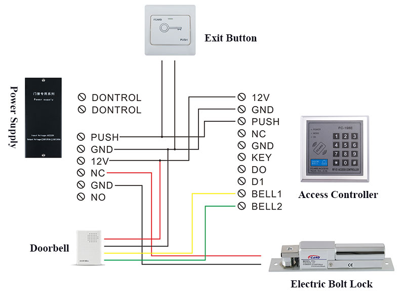
Electric Bolt Lock Fcard Premium Electric Lock Series Fcard
5-Wire Door Locks. 5-wire door locks are a bit more complicated. While the switch is off, both wires (lock and unlock) are grounded. When the switch is pushed for example to the unlock position, the unlock wire gets disconnected from the ground, and connected to +12v, activating the actuator.
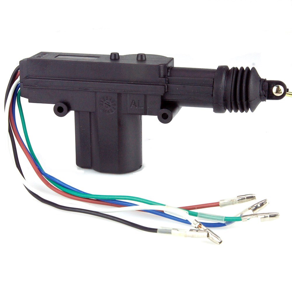
Door Lock Actuator 5 Wire Car Builder Kit Classic Car Parts Specialist
EXTRA INFORMATION: NOTE #1: Vehicles WITHOUT a FACTORY KEYLESS use a TYPE C Door Locking System and Vehicles WITH a FACTORY KEYLESS use a Chrysler 3/5 Wire Door Lock System, to connect, See DIAGRAM....."EXTRA NOTE".... on some KEYLESS ENTRY SYSTEMS, look for a ORANGE/BLACK and a PINK/BLACK these wires may work as a TYPE A Door Locking system.
Power Door Locks Don T Work Ricks Free Auto Repair Advice Ricks Free Auto Repair Advice Automotive Repair Tips And How To
POWER DOOR LOCK (5-wire reverse polarity) LT. BLUE Harness Coming Into Vehicle From Driver's Door Or Harness In Driver's Kick Panel POWER DOOR UNLOCK (5-wire reverse polarity) BLACK/WHITE Harness Coming Into Vehicle From Driver's Door Or Harness In Driver's Kick Panel PARKING LIGHTS (+) BROWN At Light Switch Or Driver's Kick Panel
Enhgfe4r Power Supply 12v 3a Utk Rfid Access Door Lock Control Switch Mode Bgde04t Shopee Indonesia
Door Locks - 5 Wire Alternating 12 Volts Positive (Type C) Relay Wiring Diagram. How to Wire Automotive SPDT Relays. Door Locks - 5 Wire Alternating 12 Volts Positive (Type C). The switch, when moved in either direction, applies both power and ground directly to motor legs without the use of any relays. Except, at the switch in this case, both motor legs rest at ground .

Thebluebeans Com Universal 4 Rocker 5 Wire Switch Kit Door Lock Power Windows 12v For 4 Doors Auto Parts And Vehicles Car Truck Interior Switches Controls
Wiring Diagrams 1. Understanding Diagrams Page U-1 Lighting Systems 1. Headlights Page L-1 2. Turnsignals & Hazard Page L-2 3. Stop Lights Page L-3 4. Backup / Horn Page L-4 Accessories Systems 1. Power Windows Page A-1 2. Power Mirrors Page A-2 3. Door Locks Page A-3 4. Clock & Cig Lighter Page A-4 5. Front Wiper & Washer Page A-5 6. Blower ...

5 Wire Door Lock Wiring Diagram Diagram Base Website Wiring
Single Wire Power Door Lock Systems Type F Type G Type H
3

Wiring Alarm Mobil

Suzuki Swift Gls Remote Central Locking Wiring Suzuki Forums
R49 Car Alarm Receiver User Manual Rf 215 Install Advance Security
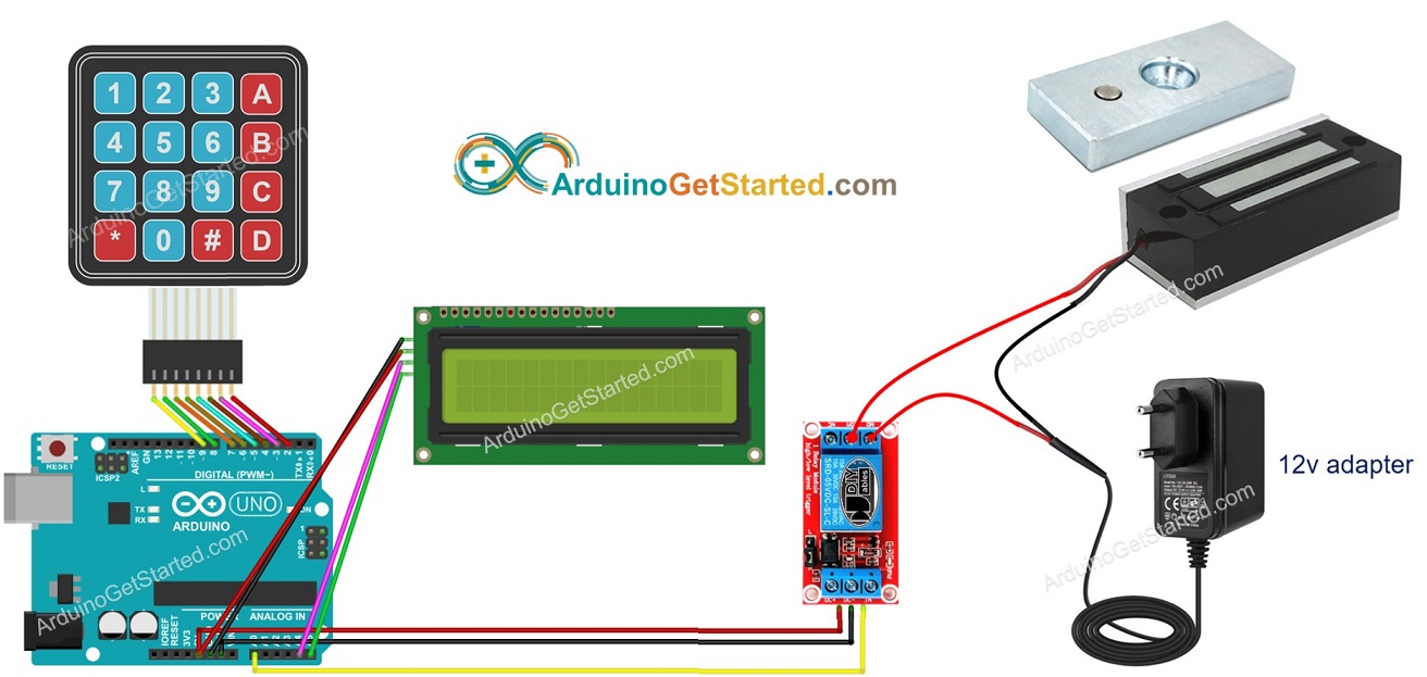
Arduino Door Lock System Using Password Arduino Tutorial

Jual Dropbolt Frameless Glass Door Drop Bolt 5 Wire Electric Lock Delay Di Lapak Nopshabits Bukalapak

Door Lock Wiring Vw Vortex Volkswagen Forum

Universal Car Door Lock System Strong Output 2 Wires And 5 Wires Actuators 360 Degree Rotation Circle Head Waterproof Design Lock Wire Lock The Doorlock Double Doors Aliexpress

Ficbox Universal Car Door Lock Vehicle Keyless Entry System Auto Remote Central Kit With Control Box Amazon Ae Electronics

Power Door Lock Actuator Wiring Diagram Door Locks Electrical Wiring Diagram Door Switch
Universal 12v 2 5 Wire Cable Car Auto Center Control Locking System Single Gun Type Central Door Lock Actuator Motor Accessories Buy Central Locking System Universal Central Lock Car Central Locking System Product On
Pan06 Car Alarm Receiver User Manual Code Systems

Sydien 2 Pack 5 Wire Car Power Door Lock Actuator For Central Locking System Dc 12v Auto Locking System Motor Buy Online In Aruba At Aruba Desertcart Com Productid 96694767

Universal Heavy Duty Power Kunci Pintu Aktuator Motor 5 Kawat 12v Mobil Sistem Penguncian Actuator Single Tipe Kit Kunci Hardware Aliexpress
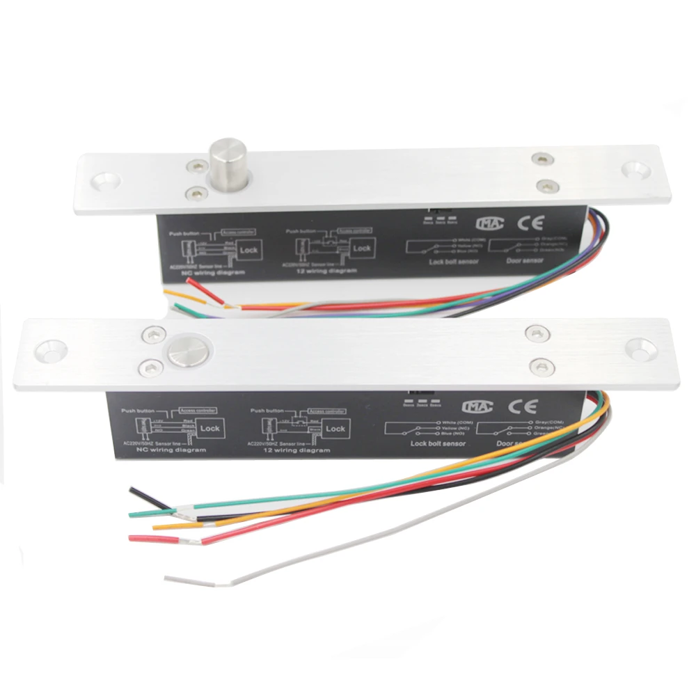
5 Wires Electric Lock Magnetic Output With Timer Dc12v Mortise Door Lock Fail Safe Fail Secure Bolt Mortise Door Lock Nc No Electric Lock Aliexpress
A1 Electric Online Store Mes Door Lock Actuator 5 Wire

Universal Car Remote Central Kit Door Lock Locking Vehicle Keyless Entry System With Remote Controllers Auto Alarm System Best Deal 4e40 Goteborgsaventyrscenter
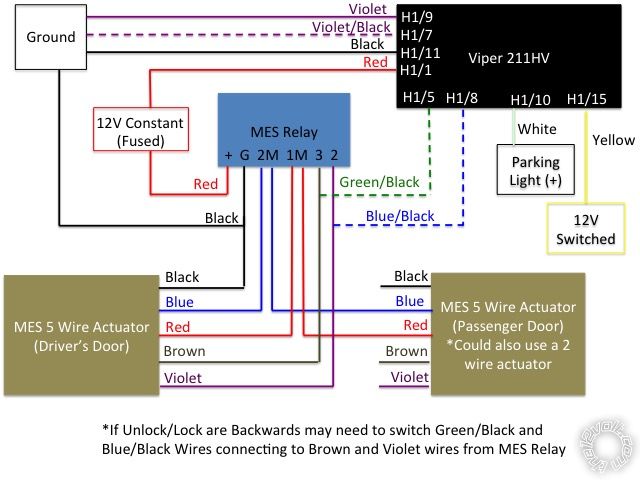
Mes Central Locking W Viper 211hv Keyless Entry
Central Locking Wiring For Honda Civic From Lf Q025a Alarm System Ecoustics Com
0 Response to "35 5 wire door lock diagram"
Post a Comment