36 battery combiner wiring diagram
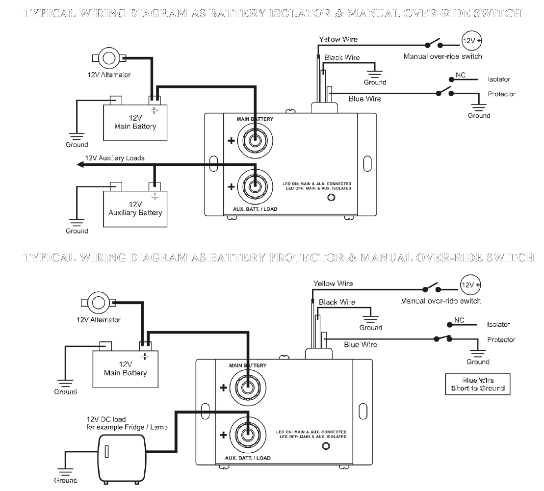
to the Battery Combiner, except for the ground wire. INSTALLATION INSTRUCTIONS: 130 AND 200 AMP MODELS The 130 and 200 amp Battery Combiners operate exactly the same as the 70 amp versions. The difference is that these mod-els use one or two contactors which are mounted externally. The gray circuit box can be mounted to any flat surface using the small mounting tabs, and the contactor(s) can ... Victron Cyrix Battery Combiner. from 40.00. Victron Cyrix battery combiners connect your house battery bank to your starter battery and alternator to allow alternator charging. Additionally, when a charge is applied to a house battery bank the Cyrix will close and allow current to flow to the starter battery.
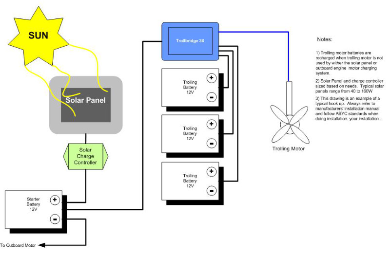
These Example System Diagrams will show how to connect the components of a solar energy system. A 2 KW, 4 KW, and 8 KW system are shown and include the solar panels, combiner boxes, charge controller (s), power inverter (s), battery bank, shunt & meter circuits, AC breaker panel, and AC generator wiring. Design your system quickly with our ...
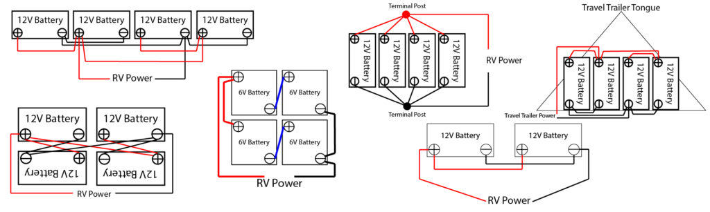
Battery combiner wiring diagram
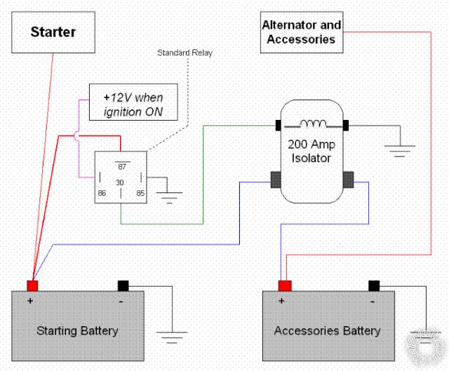
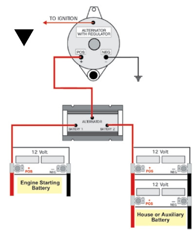
Today we will wire up a solar combiner, speficially the MidNite Solar MNPV3 combiner with 3 breakers to use on a solar array I'm setting up.Sorry about the v... Battery Alternator Wiring may Include the Following: 1. to Starter 2. to Engine terminal of battery switch 3. to Start Battery 4. to House Battery Alternator connected to a larger battery bank is most efficient. This diagram is for reference only. Alternator wiring configuration does not affect ACR installation. Engines With Separate Alternator ... Combiner is wired like the diagram below but instead of wiring to my starting battery I am wiring the forward battery off my house (connecting the + leads through the combiner as shown). I am not sure but I think I just have to upsize to handle the amperage created by the alternator charging the forward battery when the forward battery is drained.
Battery combiner wiring diagram. MNPV10-1000 and MNPV12 Combiner Instructions (continued) 6 | P a g e 10- 2 5 9 - 1 R E V : D Wiring diagram for MNPV12-250 (joined & separated) The MNPV12 has 2/0 box lugs for the plus busbars and 1/0 openings on the PV minus and ground. Battery Combiner Wiring Diagram from www.explorist.life Effectively read a cabling diagram, one offers to know how the particular components within the program operate. For example , if a module will be powered up also it sends out a signal of half the voltage in addition to the technician does not know this, he would think he has an issue, as he would expect a new 12V signal. Battery Combiner Wiring Diagram Source: bluesea.com Read electrical wiring diagrams from bad to positive plus redraw the circuit like a straight line. All circuits usually are the same – voltage, ground, solitary component, and buttons. Note: If you don't get a wiring diagram with your combiner box, they can usually be found on the manufacturer's website documentation downloads or technical support. The wiring diagrams for combiner boxes will usually be accompanied by illustrations detailing the mounting, electrical components, and the box's input and output wiring points, as illustrated below.
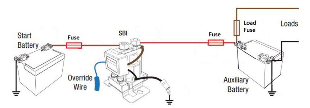
are listed: panels, cabling, combiner box, combiner box breakers, and wire fittings for the box. image - battery diagram - Battery_Diagram_1. A solar combiner box combines several solar panels into 1 DC output to connect to the The diagram below of a typical solar power system shows the component for this Simply connect a copper wire from bus bar 1 to bus bar 2 as shown. PV modules pass direct ... I used a Yandina battery combiner to connect the house and the starting battery. IRC it was under $100 us. This allowed me to use the house batteries to start the engine. Should they fail then the starter battery was in reserve. Start battery was always isolated but could be thrown into service with the house batteries or on its own if needed. In the layout shown here (for a 12 volt boat) the remote switches are Blue Sea Systems 7700 ML-Solenoids rated at 500 Amps and the ACR's are Blue Sea Systems 7622 ML-ACR Each switch or ACR comes with a remote switch, and for this layout you would end up with a total of five remote switches. Each remote switch has an indicator light to show the status of its operation.and the ON-OFF switches ... 1.8.4 Check the DC wiring to the battery, according to the wiring diagram you selected from the table on page 6. Check the connections and verify that all are securely connected. 1.8.5 Check connections to the battery and the switch setup as described earlier in this document. 1.8.6 Check connections to the meter.
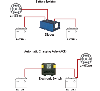
Proper battery management, including switching and charging, is essential for safe and reliable operation. The following basic wiring diagrams show how batteries, battery switches, and Automatic Charging Relays are wired together from a simple single battery / single engine configuration to a two engine, one generator, and four battery bank system. On this website we recommend many pictures abaout Battery Combiner Wiring Diagram that we have collected from various sites Wiring Diagram – strategiccontentmarketing.co, and of course what we recommend is the most excellent of picture for Battery Combiner Wiring Diagram.If you like the picture on our website, please do not hesitate to visit again and get inspiration from our website. In this wiring diagram, Victron Energy shows how you can integrate other battery manufacturers lithium batteries into a fully integrated Victron system. This system uses three 48 Volt 5000VA Quattro Inverter Chargers in a three-phase system. The IQ Combiner 3 is an outdoor-rated, NRTL-certified NEMA type 3R enclosure containing an Enphase IQ Envoy™, circuit breakers, and wiring for IQ Envoy connections. Use the IQ Combiner 3 for single-phase applications and to support the AC connections needed for an Enphase residential solar installation.
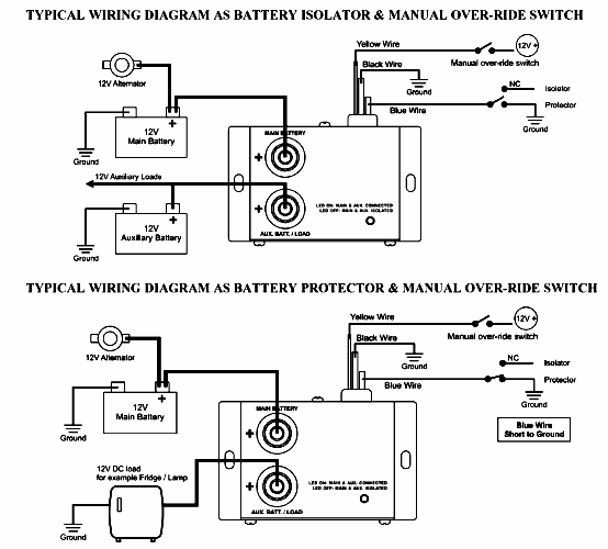
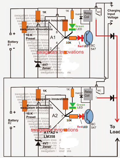
Battery combiners will put two battery banks in parallel when there is charging voltage but leave the batteries isolated during discharge. Battery combiners operate based on a specific voltage so the batteries are parallel when charging (i.e. parallel at 13.3 VDC) but isolated when discharging (i.e. disconnect when voltage gets to 12.8 VDC).

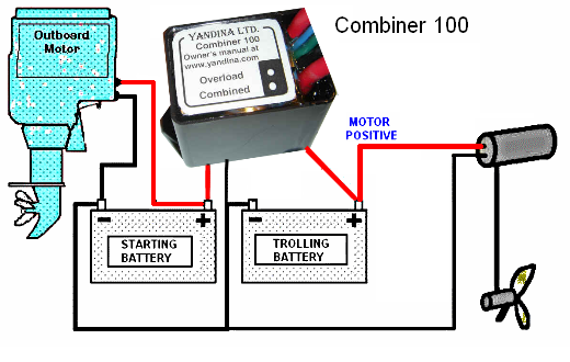
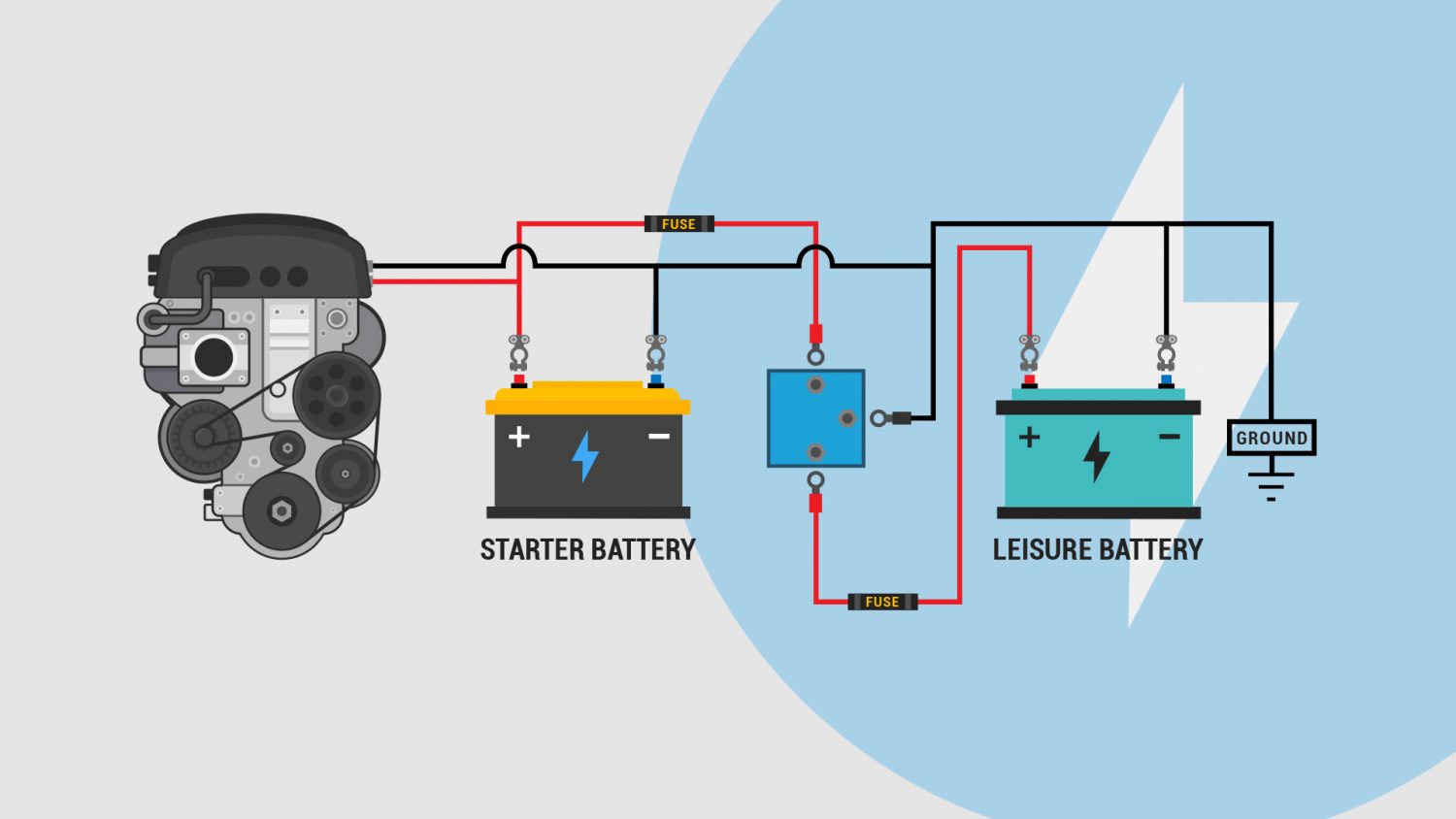
We always use battery combiners with outboard engines. Here is some general advice, when installing a battery isolator, you need to make sure that your Alternator positive is only connected to the battery isolator and NOT the starter solenoid as normal. In most cases, it's a simple as running a new large enough wire (meet's ampacity and ...
FLEXware PV-8 Combiner Wiring Sample (Circuit Breakers). Wiring Diagram. . Connect all wires to the fuse holders or circuit breakers and the box lugs. The MNPV6 PV combiner is designed to work with a custom deadfront to hide wiring when . Go to wiringall.com to get wiring diagrams for each. FCC Compliance. This equipment has been tested and found to comply with the limits for a Class B digital ...
It is best to refer to solar PV combiner wiring diagrams for more details. Plug the solar panel wire into a single pair of MC4 connectors on the combiner box. Connect the hurting wire adjacent to the blanket breaker via the output connector. Fasten it with screws. Pass the positive and negative output wires through the holes labeled DC Output.
Battery Combiners allow two and sometimes, more than two, battery banks to be automatically combined (connected) together during charging allowing a single charge source to charge multiple battery banks.. Many combiners offer manual override so that the battery banks can be connected together for use during an emergency or high power demand situation.
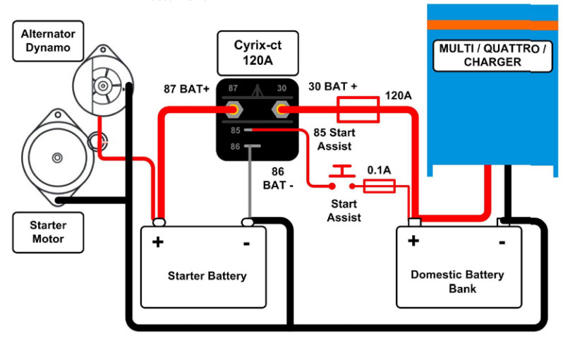
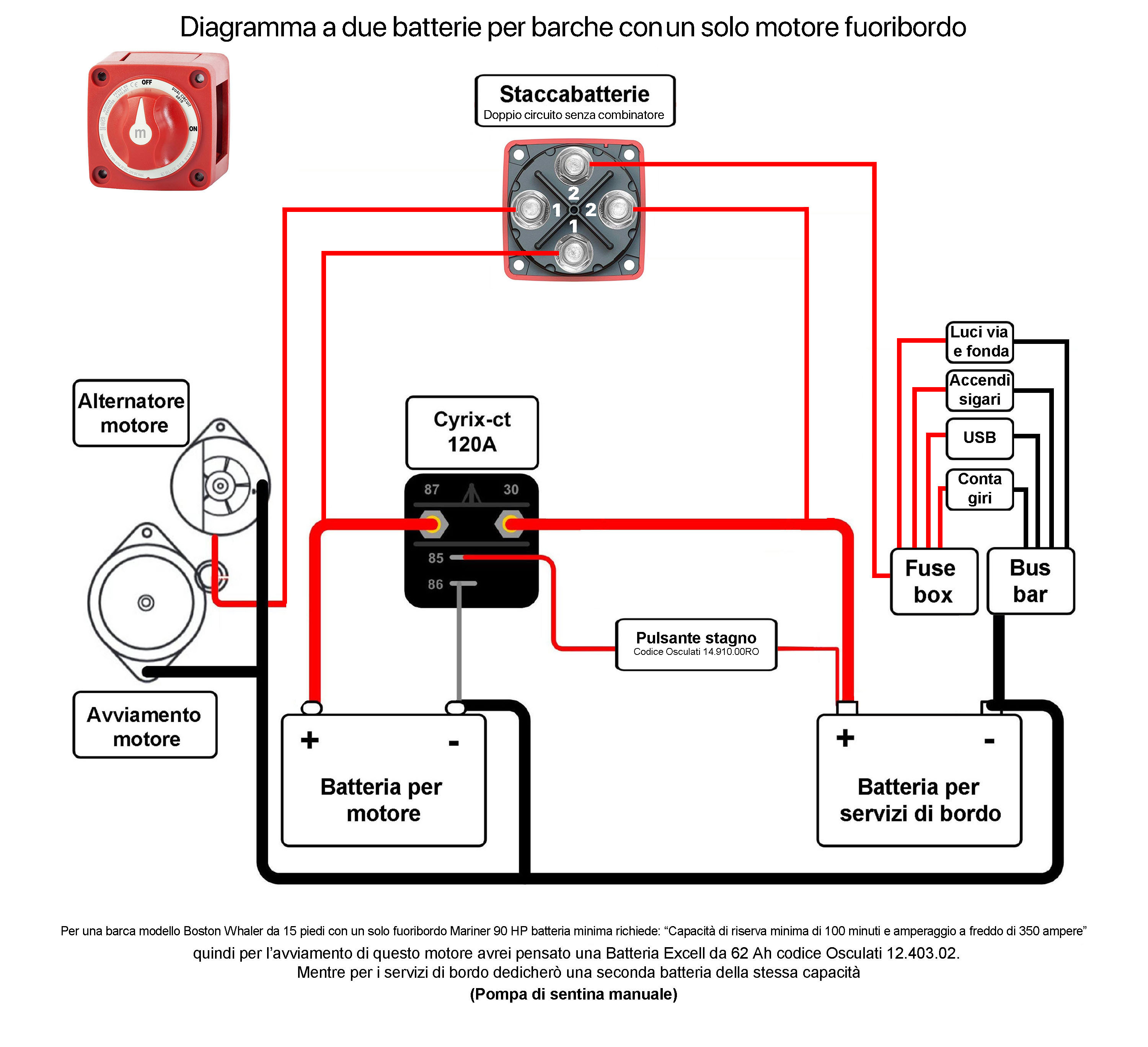
12V Wiring diagram Cyrix CT120 and shuntless ammeter. I'm designing the electrical system for my boat which I'm building step by step. I split up the start- and service battery with a Cyrix CT120 and want to measure the current of the service battery with an ammeter (+/-60A). In other words, I want to see if the service battery is being charged ...

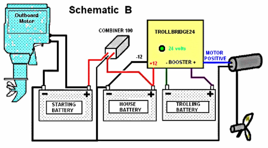
The Combiner 100 is a voltage-sensing relay (13.3 volts) which connects two batteries together when either is receiving a charge. When the charging ceases, the relay opens so that each battery operates independently. Supplemental battery banks can be added by using an additional combiner for each bank.
Quad Stack Battery Combiner Wiring Diagram (pdf) - 88 KB Ryan's Stacking (pdf) - 113 KB Ryans Clipper (pdf) - 135 KB Sam Dargan Africa Installation (pdf) - 64 KB ...
What is a battery combiner? Why should I install a battery combiner on my boat? Sign up for the PYS Newsletter: https://confirmsubscription.com/h/r/2EC1B4...

breaker for battery storage. Whole home backup with Enpower as service entrance and PV combiner connected to main load panel. This is the preferred configuration when you back up the entire main load panel, and the size of the PV combiner circuit is more than 80A. In this configuration, the PV combiner circuit connection
The instructions for the 160 amp combiner recommend a minimum wire run from the battery of 3 feet to each combiner terminal and recommend a wire size no heavier than 6 gauge. The leads come already attached with the 100 amp combiner which must not be shortened.

MNBCB 1000/50 Battery Combiner (rated at 1,000 Amps MAX). • If wiring battery cables directly to the inverter’s panel (as in Figure 1.0), consult the inverter manufacturer regarding negative wiring to a DC Negative Busbar versus a DC shunt. Refer to the third-party manufacturer’s product documentation for guidance regarding acceptable wire sizes and torque specifications when wiring to ...

A battery combiner also may fail to connect a large but discharged battery bank because the DC voltage immediately drops below the disengage value once the batteries are connected. The software of the Cyrix -ct 12/24 does more than simply connect and disconnect based on battery voltage and with a fixed time delay. The Cyrix -ct 12/24 looks at the general trend (voltage increasing or decreasing ...
The combiner will detect that the voltage has fallen and isolate the battery banks ("c" in diagram). As soon as the two battery banks are isolated, the voltage will rise again and the combiner will cycle back on—combine battery banks ("d" in diagram). This cycling will repeat over and over.
Combiner is wired like the diagram below but instead of wiring to my starting battery I am wiring the forward battery off my house (connecting the + leads through the combiner as shown). I am not sure but I think I just have to upsize to handle the amperage created by the alternator charging the forward battery when the forward battery is drained.
Battery Alternator Wiring may Include the Following: 1. to Starter 2. to Engine terminal of battery switch 3. to Start Battery 4. to House Battery Alternator connected to a larger battery bank is most efficient. This diagram is for reference only. Alternator wiring configuration does not affect ACR installation. Engines With Separate Alternator ...
Today we will wire up a solar combiner, speficially the MidNite Solar MNPV3 combiner with 3 breakers to use on a solar array I'm setting up.Sorry about the v...


0 Response to "36 battery combiner wiring diagram"
Post a Comment