40 draw the shear diagram for the beam. 7.55
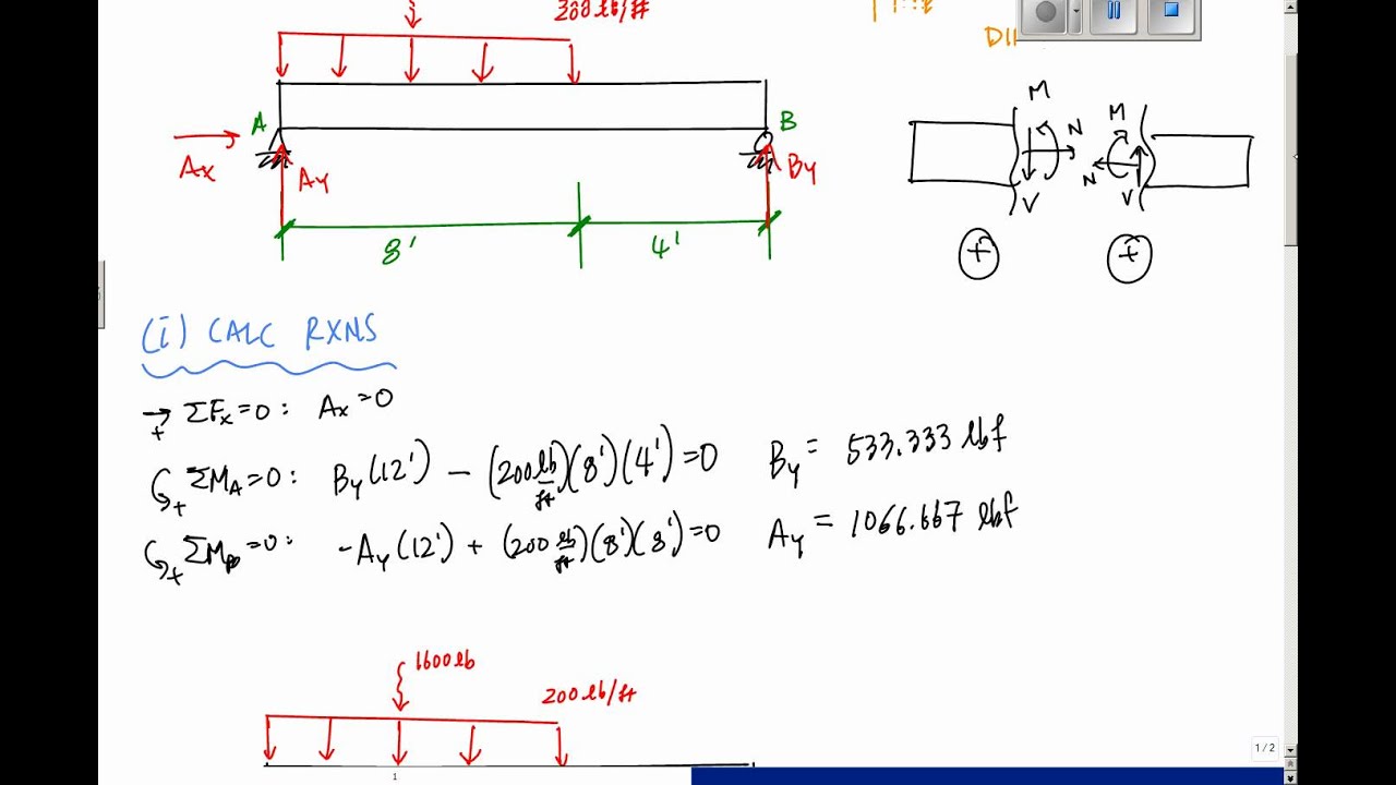
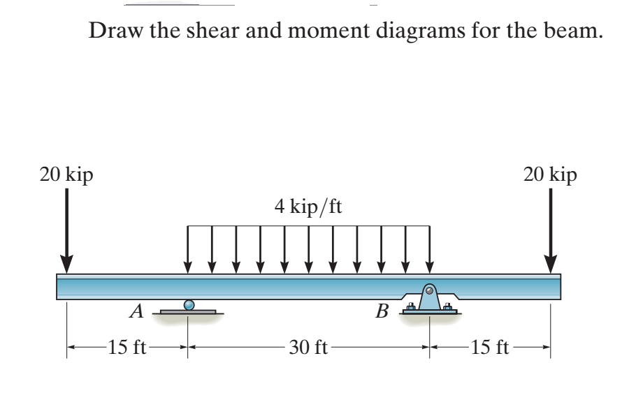
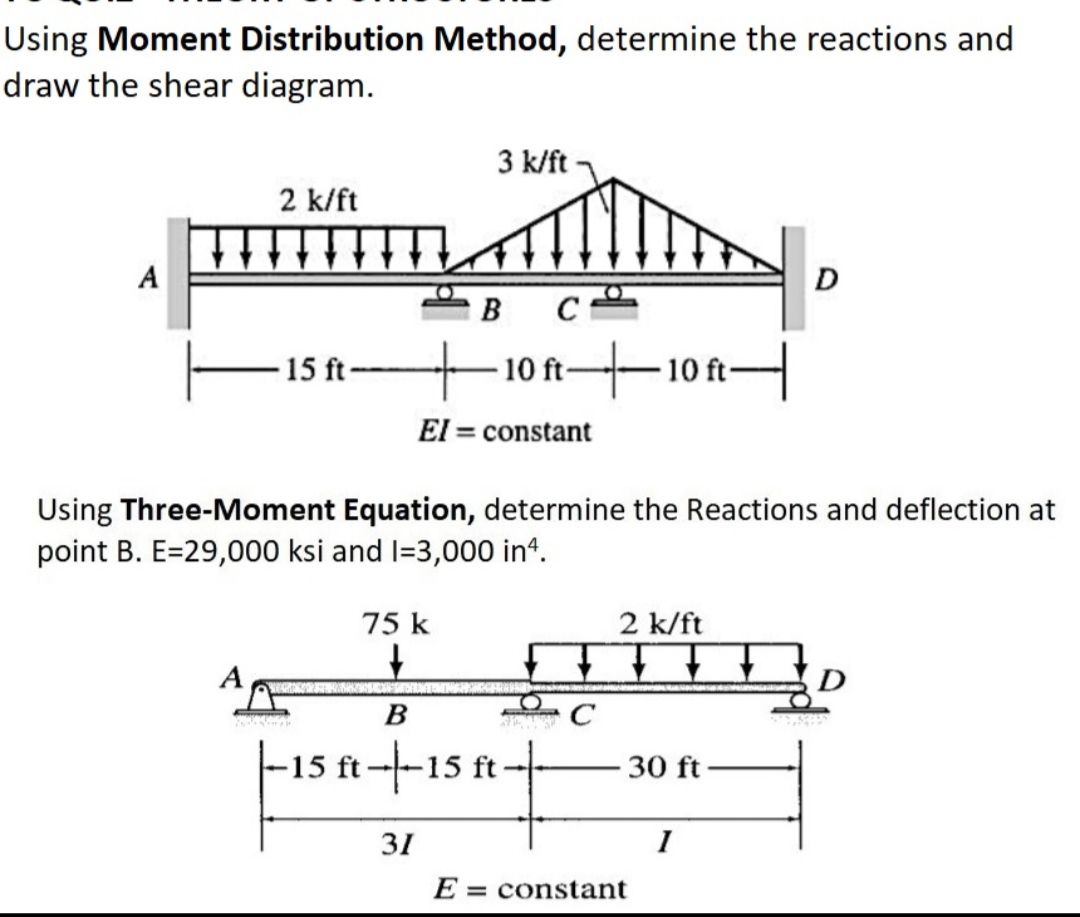
a) Calculate the shear force and bending moment for the beam subjected to a concentrated load as shown in the figure. Then, draw the shear force diagram (SFD) and bending moment diagram (BMD). b) If P = 20 kN and L = 6 m, draw the SFD and BMD for the beam. P kN L/2 L/2 A B EXAMPLE 4 Question: Draw the shear and moment diagrams for the beam.Problem 7-61 from:Engineering Mechanics: Statics, 14th editionRussell C. HibbelerThank you guys for...
Beam Calculator Online (Calculate the reactions, Draws Bending Moment, Shear Force, Axial Force) We updated the beam calculator interface and added additional features for calculating beams (calculation of statically indeterminate beams, image saving and section selection)! GO TO NEW INTERFACE (BEAM)>. GO TO NEW INTERFACE (FRAME/TRUSS)>.
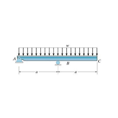
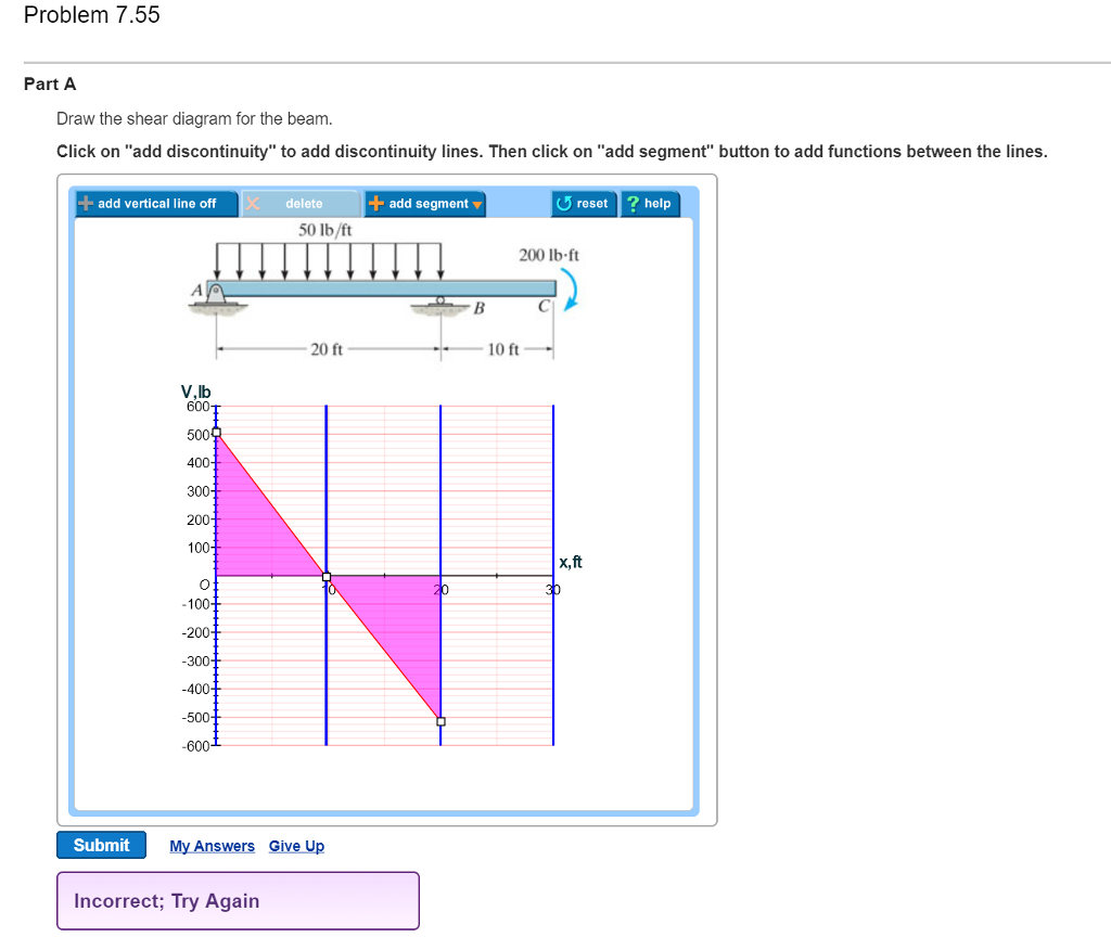
Draw the shear diagram for the beam. 7.55
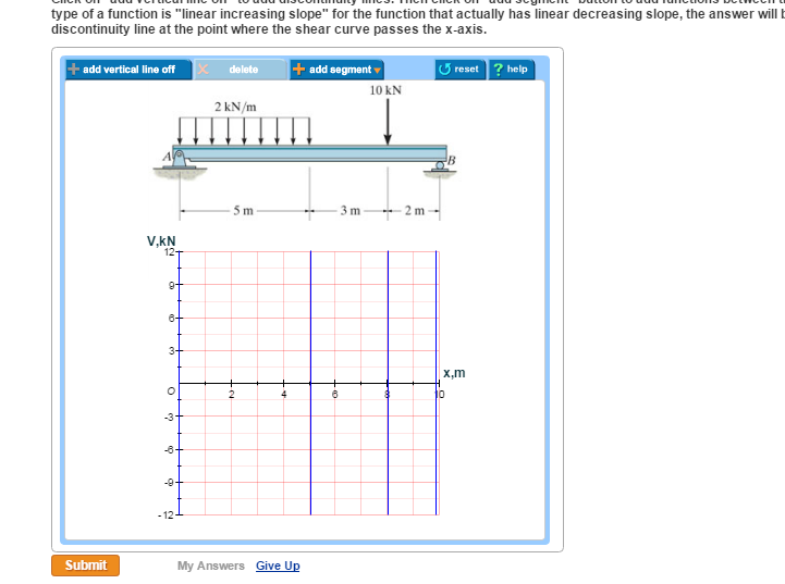
778 draw the shear and moment diagram for the beam. Draw the shear and moment diagrams for the beam. Click on add vertical line off to add discontinuity lines. Answer to problem 780 part a draw the shear diagram for the beam. Then click on add segment button to add functions between the lines. 7 78 as a picture shown. Question: KHW-28 Problem 7.55 1 of 3 Part A Draw the shear diagram for the beam. Click on "add vertical line off" to add discontinuity lines. 5 Nov 2020 — 1 Answer to Problem 7.55 Part A Draw the shear diagram for the beam. Click on "add vertical line off to add discontinuity lines.1 answer · Top answer: Consider the forces in y-direction. I Fy = 0 RA+RB =(40x8)+201
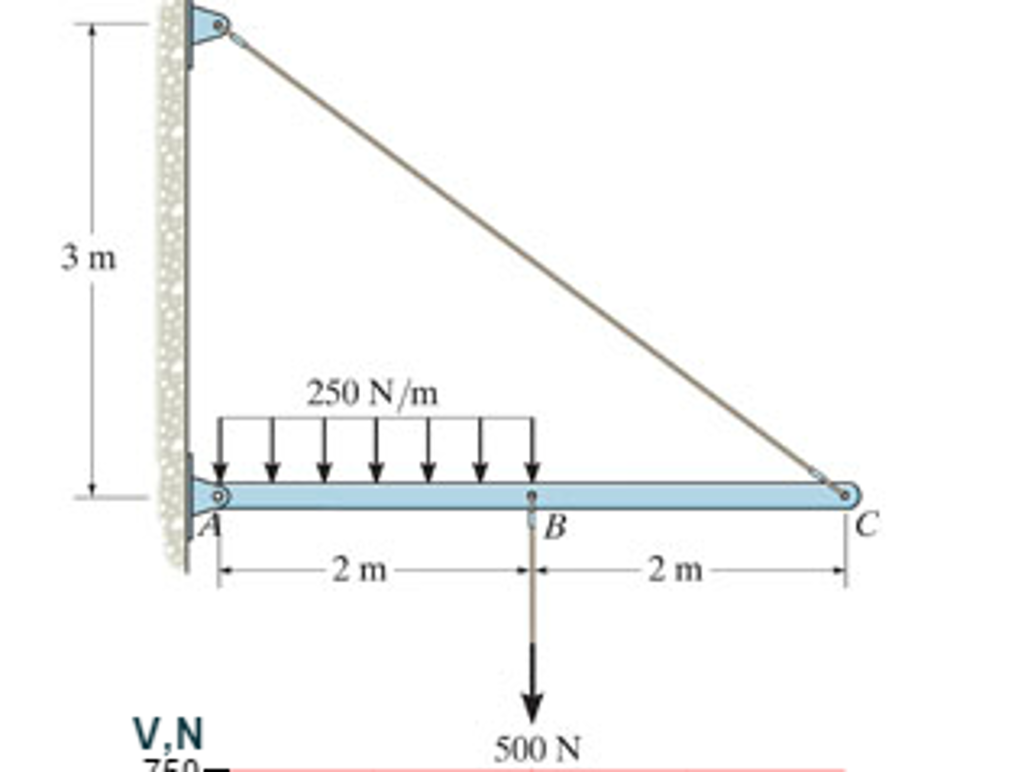
Draw the shear diagram for the beam. 7.55. Transcribed image text: Problem 7.55 Part A Draw the shear diagram for the beam. Click on "add vertical line off to add discontinuity lines. 4.3 Shear- Moment Equations and Shear-Moment Diagrams The determination of the internal force system acting at a given section of a beam : draw a free-body diagram that expose these forces and then compute the forces using equilibrium equations. The goal of the beam analysis -determine the shear force V and Solution for 7-55. Draw the shear and moment diagrams for the beam. 20 AN 40 kN/m 150 kN m 3m Many structures can be approximated as a straight beam or as a collection of straight beams. For this reason, the analysis of stresses and deflections in a beam is an important and useful topic. This section covers shear force and bending moment in beams, shear and moment diagrams, stresses in beams, and a table of common beam deflection formulas.
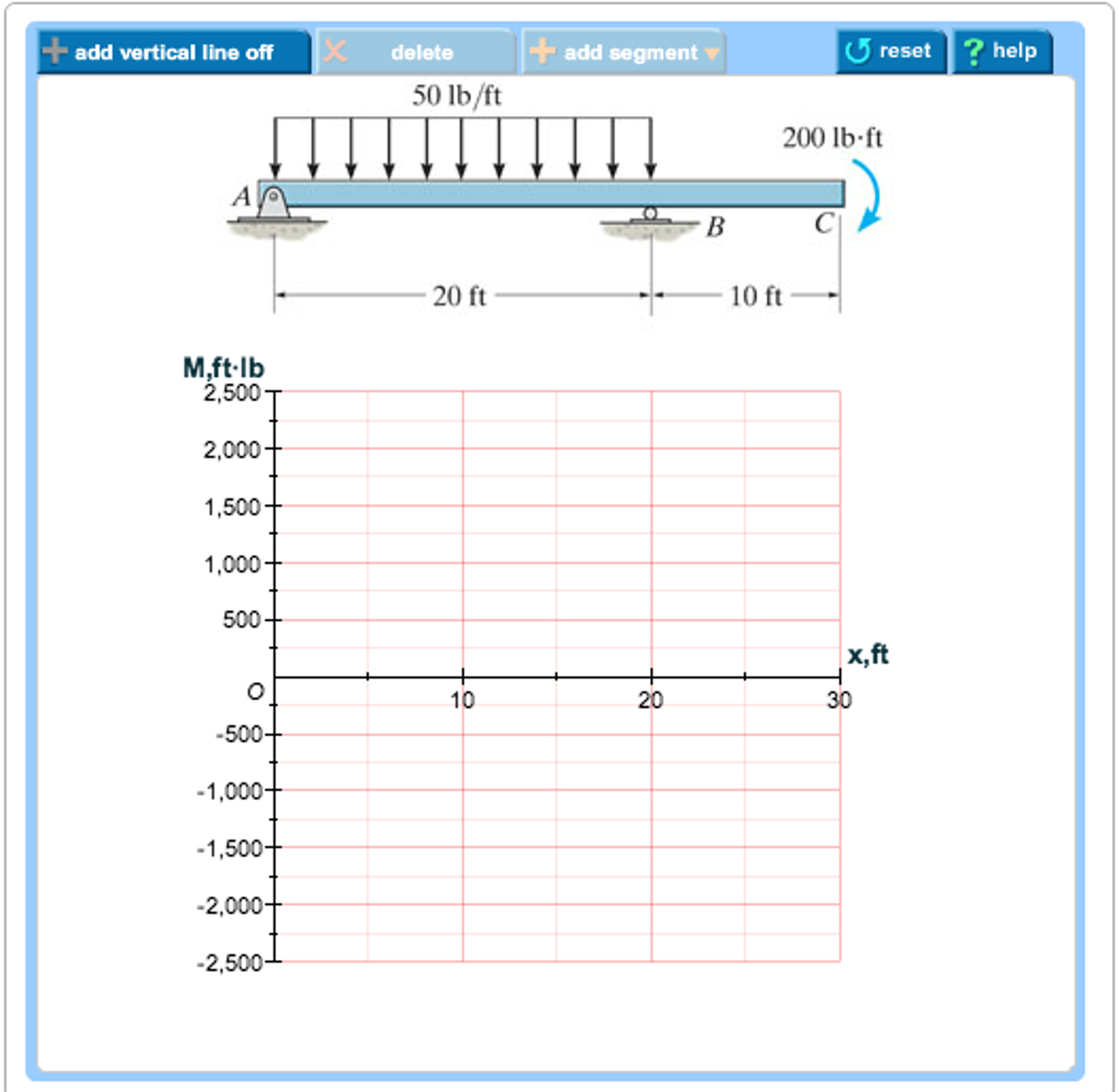
Shear and moment diagrams and formulas are excerpted from the Western Woods Use Book, 4th edition, and are provided herein as a courtesy of Western Wood Products Association. Introduction Notations Relative to “Shear and Moment Diagrams” E = modulus of elasticity, psi I = moment of inertia, in.4 L = span length of the bending member, ft. This is an example problem that will show you how to graphically draw a shear and moment diagram for a beam. In general the process goes like this:1) Calcul... Transcribed image text: Problem 7.55 Part A Draw the shear diagram for the beam. Click on "add vertical line off" to add discontinuity lines. Draw the shear diagram for the beam. Click on "add vertical line off" to add discontinuity lines. Then click on "add segment" button to add functions between ...
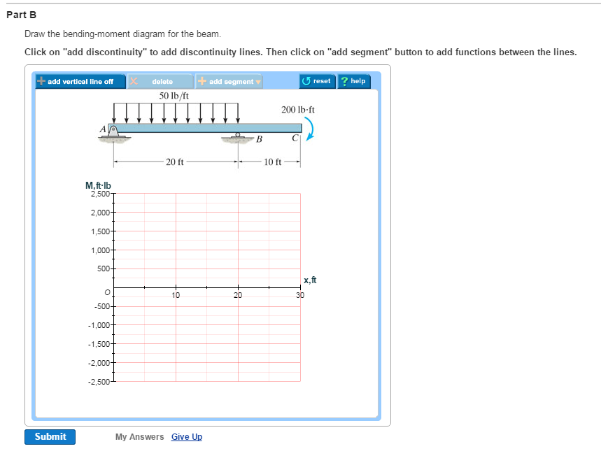
Transcribed image text: Problem 7.55 Part A Draw the shear diagram for the beam. Click on "add vertical line off" to add discontinuity lines. Transcribed image text: Problem 7.55 3 of 4 Part A Draw the shear diagram for the beam. Click on "add vertical line off" to add discontinuity lines. Transcribed image text: Problem 7.55 1 of 2 Part A Draw the shear diagram for the beam Click on 'add vertical line off to add discontinuity lines. Transcribed image text: Problem 7.55 Draw the shear diagram for the beam. Click on "add discontinuity" to add discontinuity lines. Then click on "add segment" button to add functions between the lines. 4 + 0 ? 50 lb/ft 200 lb-ft B с 20 ft 10 ft No elements selected V, 16 600 500 400 300 200 100 0 ITETI THOTTHITH I, ft 10 20 30 -100 -200 -300 -400 -500 -600 Add discontinuity lines and select ...
Select The Correct Shear Diagram For The Beam Figure 1 Study Com
Transcribed image text: Problem 7.55 Draw the shear diagram for the beam. Click on "add vertical line off to add discontinuity lines.
Draw The Shear Diagram For The Beam Home Work Help Learn Cbse Forum
5 Nov 2020 — 1 Answer to Problem 7.55 Part A Draw the shear diagram for the beam. Click on "add vertical line off to add discontinuity lines.1 answer · Top answer: Consider the forces in y-direction. I Fy = 0 RA+RB =(40x8)+201
2
Question: KHW-28 Problem 7.55 1 of 3 Part A Draw the shear diagram for the beam. Click on "add vertical line off" to add discontinuity lines.

Esteem Note Pdf Txt
778 draw the shear and moment diagram for the beam. Draw the shear and moment diagrams for the beam. Click on add vertical line off to add discontinuity lines. Answer to problem 780 part a draw the shear diagram for the beam. Then click on add segment button to add functions between the lines. 7 78 as a picture shown.
Solved Problem 7 59 Part A Draw The Shear Diagram For The Chegg Com

Drawing Shear And Moment Diagrams For Beam Youtube

Can Someone Solve A B For Me Please I Need An Accurate Draw Hw8 Shear And Moment Dlagrams Problem 7 55 Dr Homeworklib
Performance Assessment Of Steel Structures With Semi Rigid Joints In Seismic Areas Emerald Insight

Solved Part B Draw The Moment Diagram For The Beam Click On Add 1 Answer Transtutors

كتاب دكتور مشالى Volume Pdf Rivet Nut Hardware
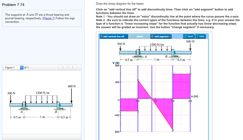
Solved Problem 7 74 Draw The Shear Diagram For The Beam Chegg Com

Solucionaro Mecanica Vetorial Para Engenheiros Capitulo 7 Solucionaro Mecanica Docsity

A Study On Mid Panel Of Steel Shear Walls With Dual Openings Sciencedirect

Can Someone Solve A B For Me Please I Need An Accurate Draw Hw8 Shear And Moment Dlagrams Problem 7 55 Dr Homeworklib
Solved Problem 7 75 Part A Draw The Shear Chegg Com
2
Drawing Shear And Moment Diagrams Example Mechanics Of Materials And Statics Youtube
Solved 7 76 Draw The Shear Diagram For The Beam Draw The Chegg Com

Hw 7 Ran Pdf Hwk 7 Due At 9 00 Am Cdt 1 Of 14 Https Session Com Myct Assignmentprintview Ass Hwk 7 Due At 9 00 Am Cdt Due 9 00am On Wednesday You Course Hero

Can Someone Solve A B For Me Please I Need An Accurate Draw Hw8 Shear And Moment Dlagrams Problem 7 55 Dr Homeworklib
Solved Problem 7 55 Part A Draw The Shear Diagram For The Chegg Com
Ijerph Free Full Text Study On Passive Heating Involving Firewalls With An Additional Sunlight Room In Rural Residential Buildings Html
Answered Draw The Shear And Moment Diagrams For Bartleby
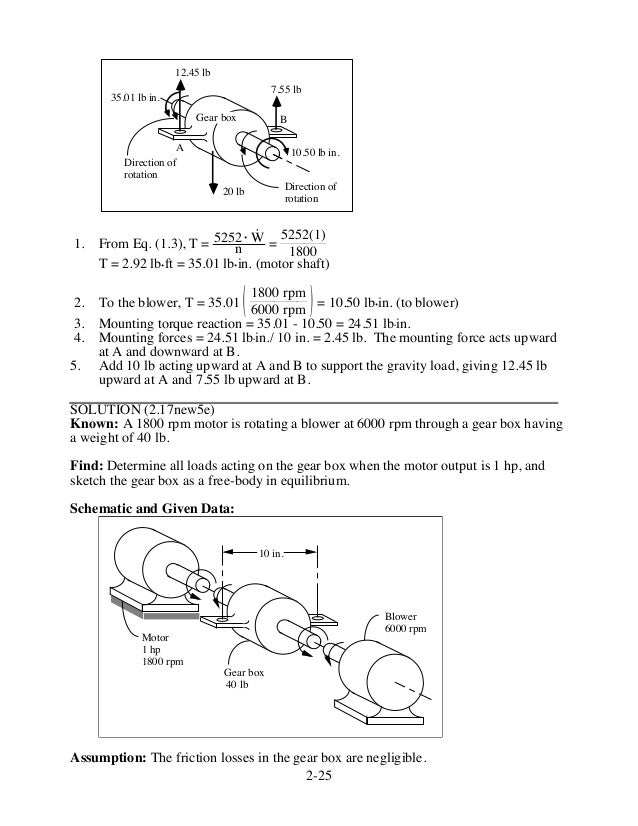
Fundamentals Of Machine Component Design 5th Edition Juvinall Solutio

Diseno De Losas Metodo Aci Docsity

Can Someone Solve A B For Me Please I Need An Accurate Draw Hw8 Shear And Moment Dlagrams Problem 7 55 Dr Homeworklib
2

Pdf Characterization And Application Of Frcm As A Strengthening Material For Shear Critical Rc Beams

Scielo Brasil Experimental Studies On Shear Resistance Performances For The Shear Key Of H Shape Steel Spatial Grid Roofs Experimental Studies On Shear Resistance Performances For The Shear Key Of
Monotonic Behavior Springerlink
Solved Problem 7 55 Part A Draw The Shear Diagram For The Chegg Com
Dash4ghoyq Rom
K5s1t0sjciecim

Investigation Of The Infill Plate Boundary Condition Effects On The Overall Performance Of The Steel Plate Shear Walls With Circular Openings Sciencedirect
Gravity Dams Springerlink

Comprehending The Ductile Behavior Of Slotted Bolted Connections Shu 2017 The Structural Design Of Tall And Special Buildings Wiley Online Library
Page 16 5 11 04 High Resolution Stock Photography And Images Alamy

Estimation Of Inelastic Interstorey Drift For Osb Gypsum Sheathed Cold Formed Steel Structures Under Collapse Level Earthquakes

Hw 7 Ran Pdf Hwk 7 Due At 9 00 Am Cdt 1 Of 14 Https Session Com Myct Assignmentprintview Ass Hwk 7 Due At 9 00 Am Cdt Due 9 00am On Wednesday You Course Hero
Rx Pqcormabyem
0 Response to "40 draw the shear diagram for the beam. 7.55"
Post a Comment