39 electric door strike wiring diagram
CAUTION: Fail-safe is not permitted with the UL Fire Door. Accessory label. Strike Input - Minimum Wire Gauge Requirements. Voltage 100 ft 150 ft 200 ft 250 ft ... Next: · Relays...How Do They Work? · HES8500 electric strike install video · How to Wire a Door Strike to an Algo 3226, 3228 and 8028 Doorphone.
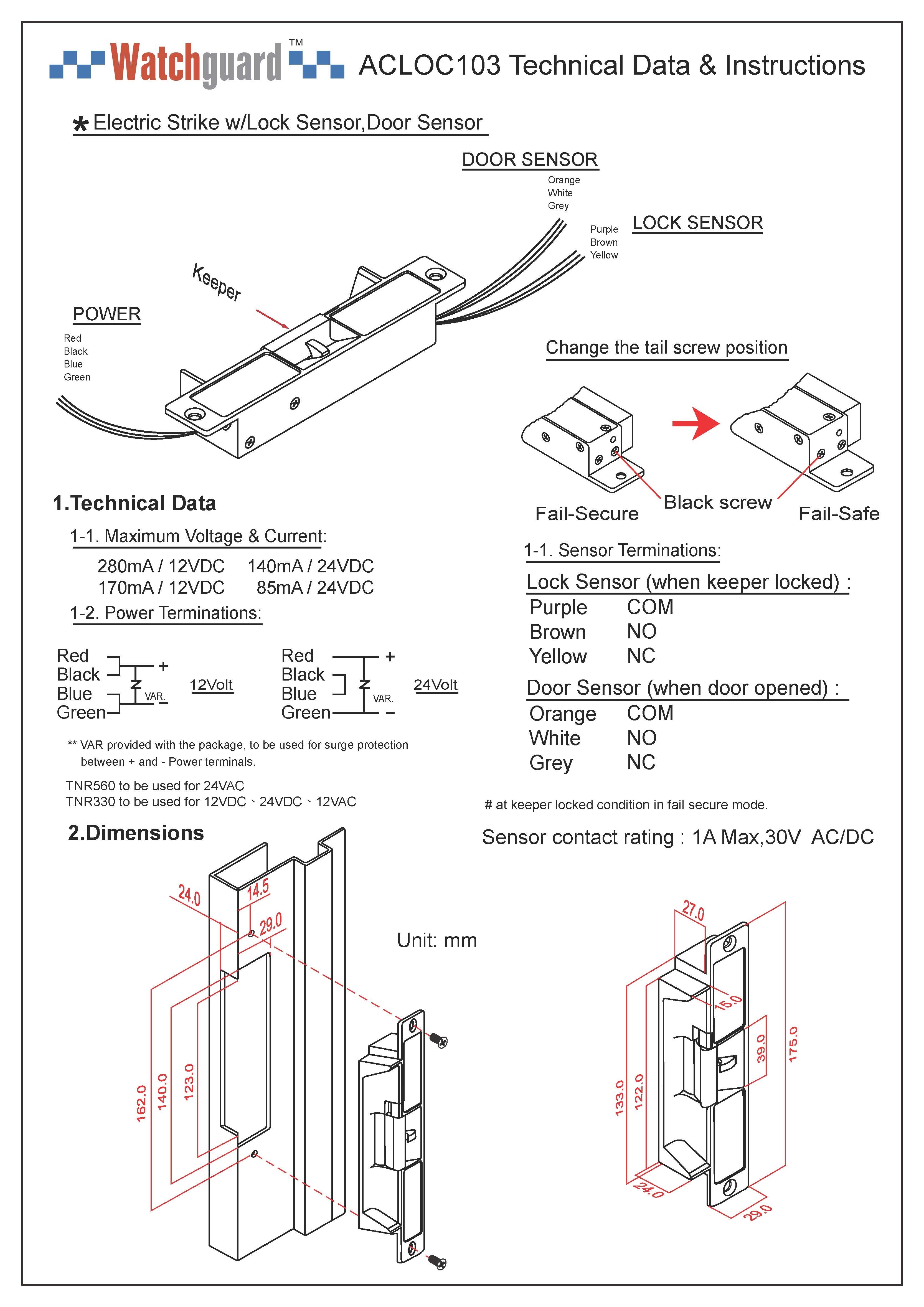
Electric Door Strike Wiring Diagram Valid Ip68 Access Control. Hes Electric Strike Wiring Diagram Valid. 24V, see Diagram 2. 2. 9600-12/ 24-630. If your strike is supplied with the LATCHBOLT MONITOR (LBM), or LATCHBOLT STRIKE MONITOR (LBSM), see Diagrams 3 & 4 for wiring instructions. 3. For available faceplate options, see page 4.
Electric door strike wiring diagram
Source: doorentrydirect.com. Size: 82.15 KB. Dimension: 800 x 565. DOWNLOAD. Wiring Diagram Pictures Detail: Name: adams rite electric strike wiring diagram - Adams Rite 7131 Electric Strike For Aluminum Stile W 4500 4700 Deadlatches Installation Instructions ES7131 0 80 0180 361 H 381. File Type: JPG. illustrated within Diagram 2. 2. If your strike is supplied with the LATCHBOLT MONITOR (LBM), or LATCHBOLT STRIKE MONITOR (LBSM), see Diagrams 3 & 4 for wiring instructions. 3. For available faceplate options, see page 4. Prepare Strike CAUTION! Before connecting any device at the installation site, verify input voltage using a multimeter. 1. Check power source and make sure that the electric strike is configured to the appropriate voltage. This electric strike ships as 12V. If you need to convert the unit from 12V to 24V, see Diagram 2. 2. If your strike is supplied with the LATCHBOLT MONITOR (LBM), or LATCHBOLT STRIKE MONITOR (LBSM), see Diagrams 3 & 4 for wiring instructions. 3.
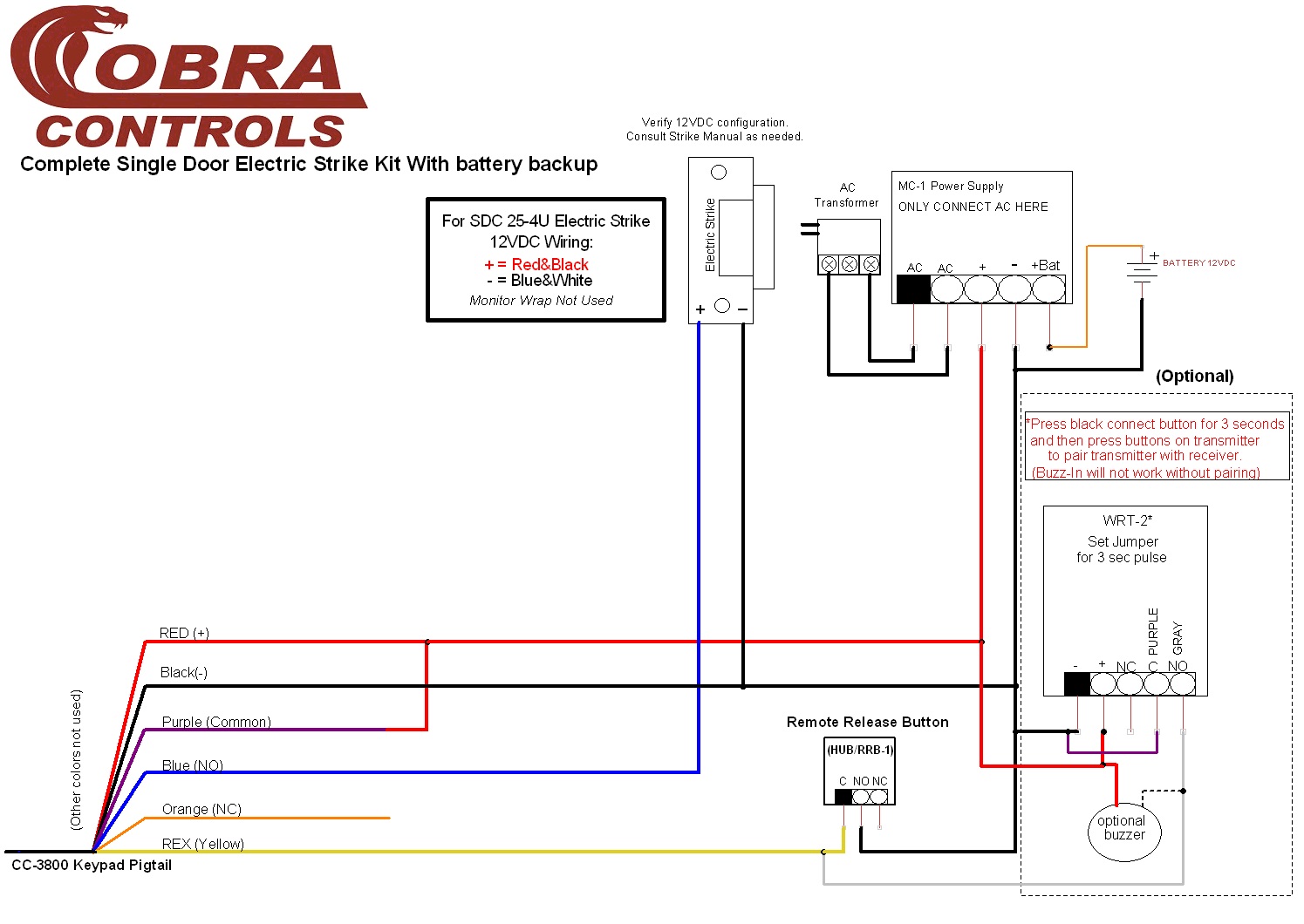
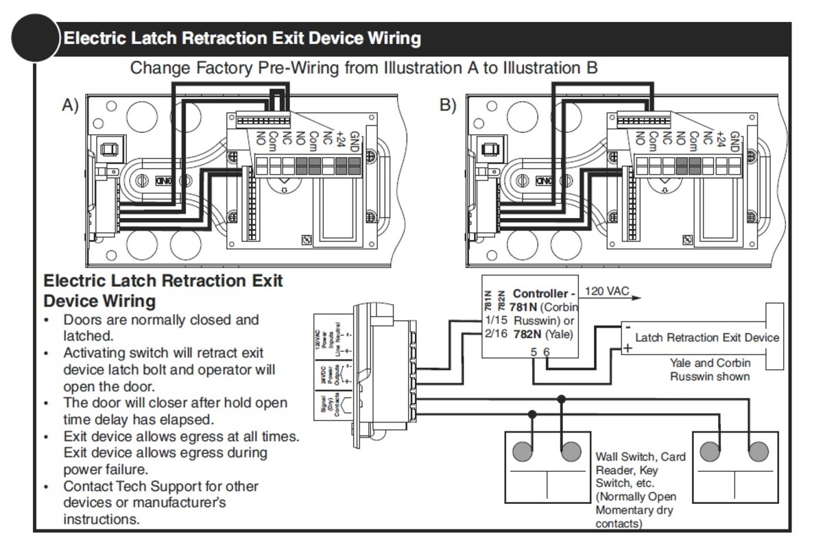
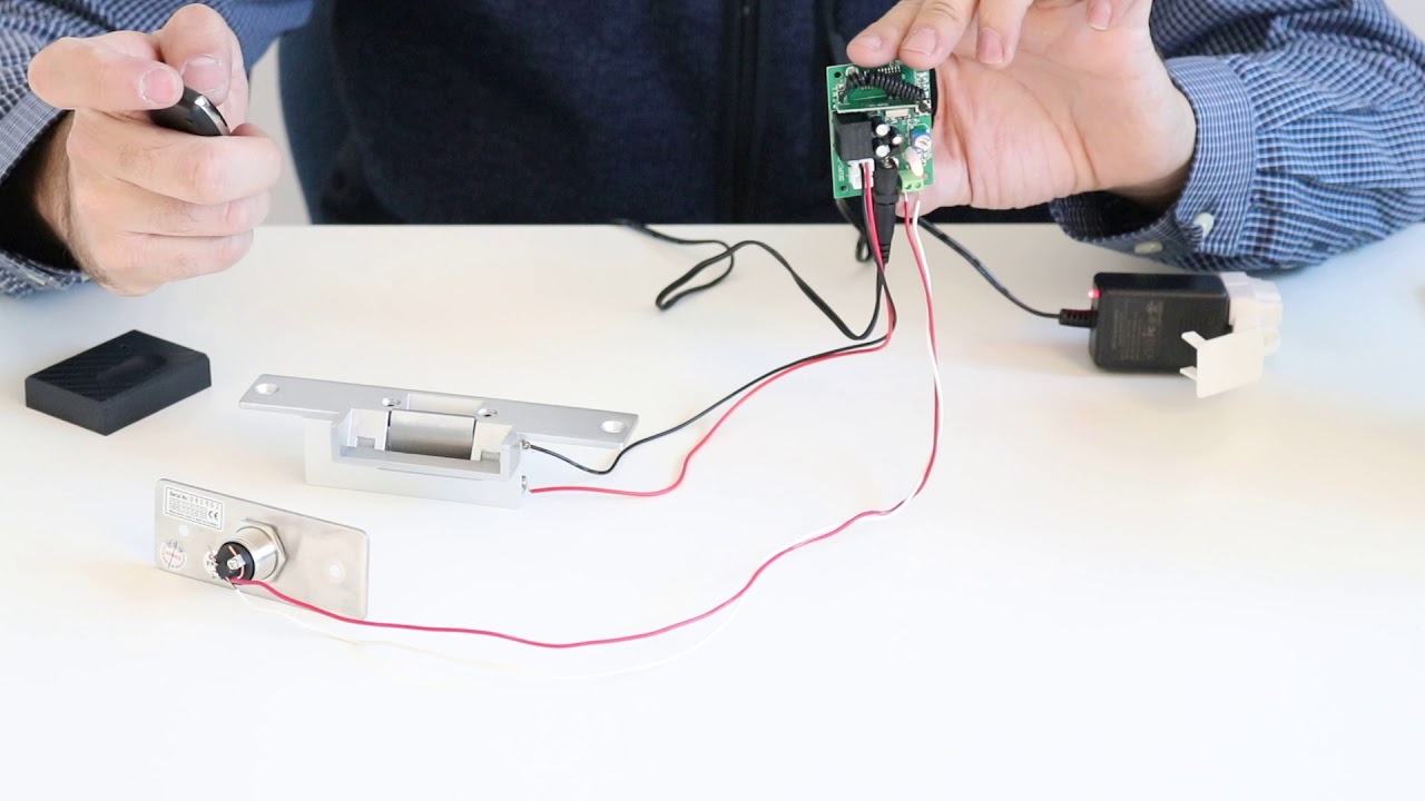
Electric door strike wiring diagram. electric door strike wiring diagram . electric door strike wiring diagram . fast trac form . riser drawings for auto operators . Common Wiring D . quote request form . can automatic door opener work with and card reader strike . quote request form ... We show you how an electric strike works with a remote door opener and a push to exit button. This is a simple electric strike setup with a manual push to ex... devices requiring power such as electric locks, electric strikes, and electric latch retraction exit devices. Features and Benefits • Available with most 2-, 3-, and 5-knuckle bearing hinges • Available with 2, 4, 6, 8, 10 or 12 wires • Wires are contained within the hinge- invisible and tamperproof he electric strike wiring diagram mag lock wiring diagram. cobra controls acp 1t 1 door computerized access control A set of wiring diagrams may be required by the electrical inspection authority to assume relationship of the domicile to the public electrical supply system.
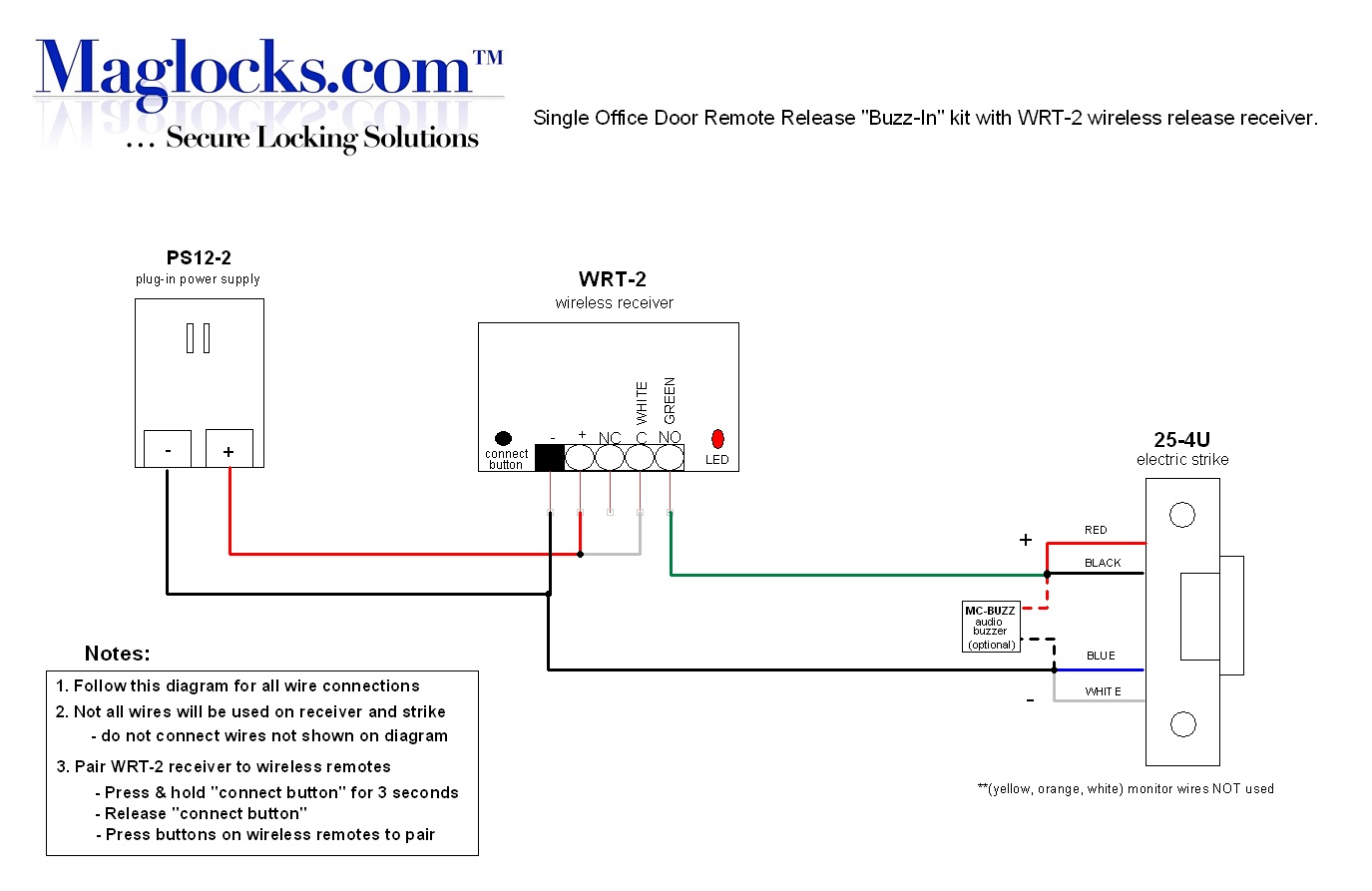
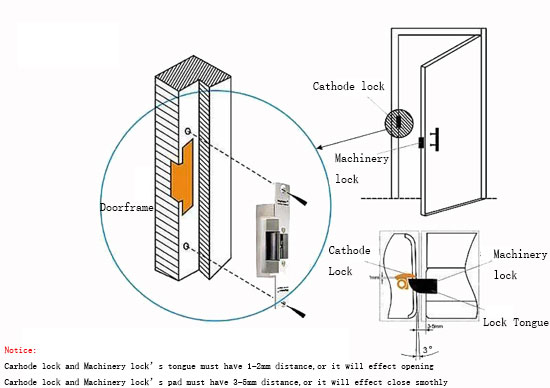
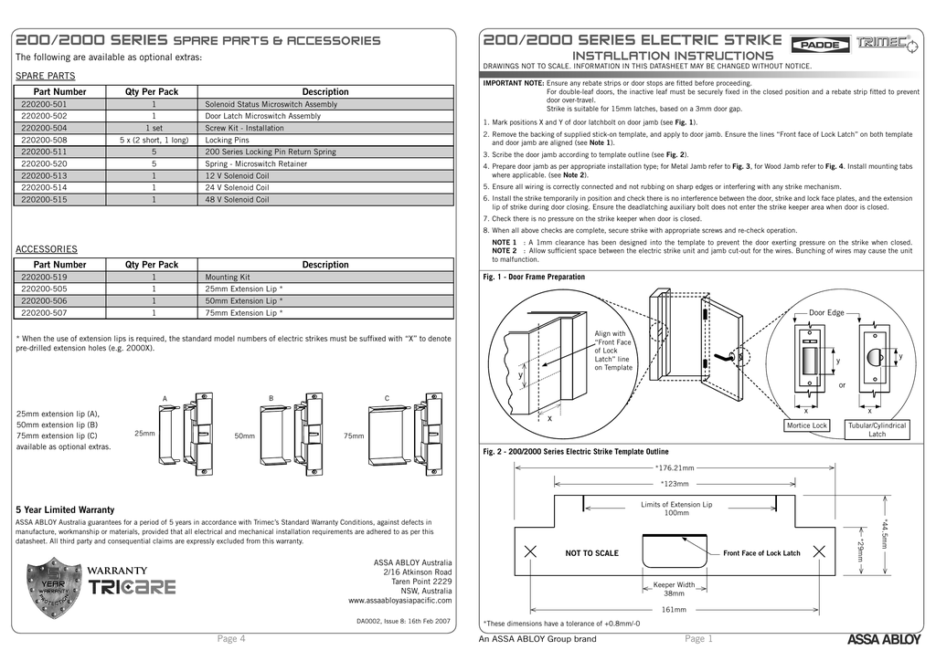
Common wiring diagrams. Resolution: The following common wiring diagrams are available:One Single Door with Panic BarElectric Latch Retraction, with Auto OperatorDelayed egress - Fire Rated ApplicationAuto Operator and actuatorElectr... Resolution: Electronic Protocols:Access Control Door with electric trimAccess Control with electric strike ... The Folger Adam 300 electric strike is a solenoid operated device. 1. NON-FAIL-SAFE. When power is applied the solenoid pulls the locking cam into the unlocked. To enable the Electric strike to be located in the door frame, first mark the position of the Door Latch front face on the door frame with the door in the closed position, ('X ' mm). ... The wiring diagram for the monitoring schematic is shown in Fig. 4 and on the back of the strike. ASSA ABLOY Australia Pty Limited, 235 Huntingdale Rd ... Wiring A Strike To Single Io Door Controller Prodatakey Inc. Wiring diagram fail secure electric strike connection cornick how to wire with a mag lock access control cables and step 60 silent steplock single door remote buzz in kit installation instructions 7400 your table of contents standard for rim strikes rci dormakaba basics dengarden schematics io basic wireless release system 5 wires ...
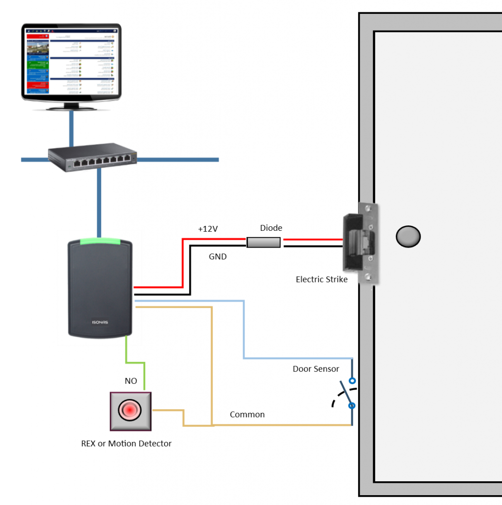
GSC3570 Connection & Wiring Diagrams - "Fail Secure" Electric Strike, POE Power Supply Outdoors-+ Fail Secure Electric Strike Door Connect Indoors Motion Sensor-+ S Power Supply 12V GND Exit Button +12V GND IN+ AIN1 NC1 AIN3 AIN2 COM1 NO1 GND POE power supply 802.3af 12.5W IN + Active voltage range 9-15V POE Switch Ever wanted to install your own electric door strike, but confused about the whole wiring it up. In this guide we take a FES10 NC/NO ... Search Wiring Diagrams for HES and Securitron products. Use the fields below to narrow down your search. You can also view all Wiring Diagrams by leaving the fields blank and clicking the "Search" button. PRO TIP: Be Broad! There are additional filters on the Results page to further narrow down your search. Magnetic Lock Wiring Diagram. Much like the door access control system diagram above, the mag lock wiring diagram relies on a few simple basics: electricity supply, switches, and, of course, locks. Magnetic locks, also referred to as mag locks or maglocks for short, rely on a constant flow of electricity to stay sealed. When that power is cut ...
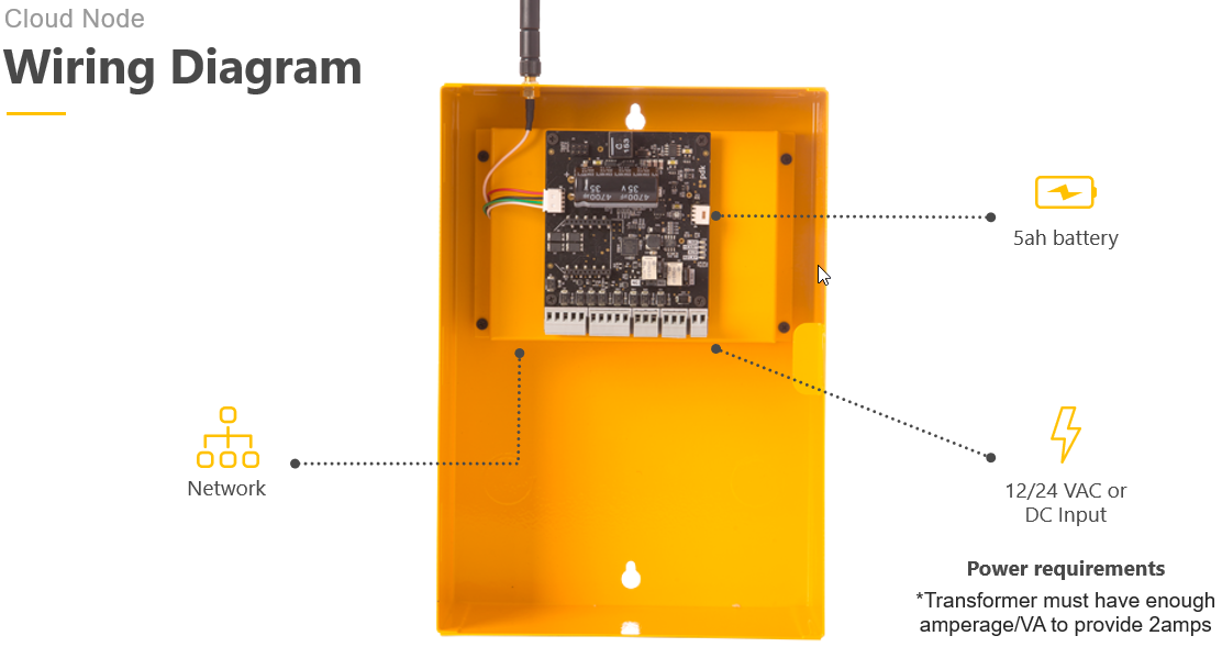
In this diagram, you can see the basic wiring for Kisi's access control system with an electric lock. The one in the diagram is a magnetic lock, but the premise is the same for an electric strike.
Hes 5000 Series Electric Strike Wiring Diagram Sample. hes 5000 series electric strike wiring diagram - What's Wiring Diagram? A wiring diagram is a type of schematic which utilizes abstract pictorial signs to show all the affiliations of elements in a system. Wiring layouts are made up of 2 points: icons that represent the elements in the circuit,…

Horton electric strike interface module for automatic doors Horton C7220-1. Home ... Door Closers > Automatic Door Openers > Parts > Horton > 4000 Hercules > Swinger > Electric Strike Interface Module. ... The Wiring Diagram for this unit (everything we have), can be reviewed here:
Electric Strike Kit: https://amzn.to/2VjiwogExtra Push Entry Clickers:https://amzn.to/2EbUAfzLow Voltage Wire: https://amzn.to/2EvMuQkIn this video we show y...
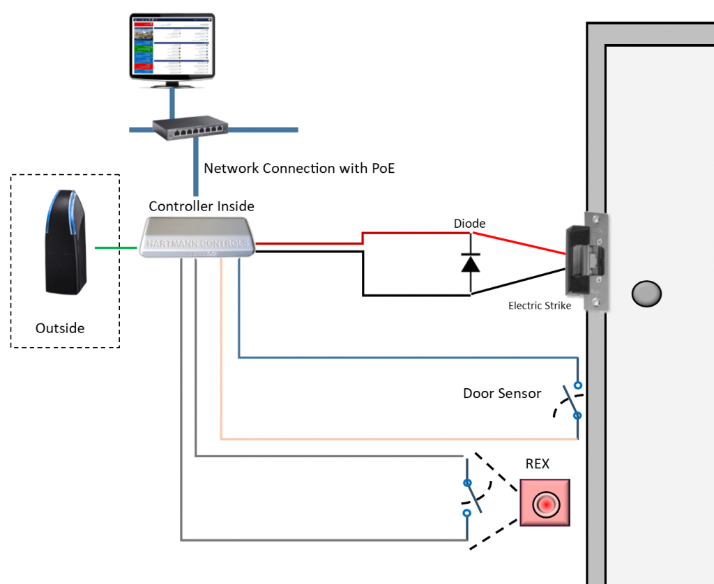
GSC3570 Connection & Wiring Diagrams - “Fail Secure” Electric Strike, POE Power Supply. Outdoors. -. +. Fail Secure Electric Strike. Door Connect. Indoors.
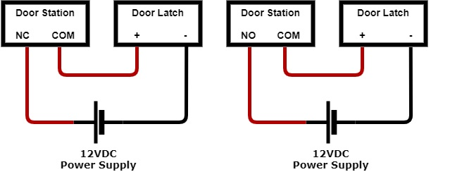
Discussion Starter · #1 · Jan 1, 2006. Hi, I have just installed an electric door strike/release contraption. I have it wired up to an intercom unit that has it's own door release function but it it has a delay which means if the person outside doesn't push the door when i push the button, there is a 30 second delay before i can release the ...

FOR WOOD DOOR APPLICATIONS SPACER ASSY OPTIONAL KIT P/N WDC7400 SHIM KIT P/N 91-0933 TYPICAL ELECTRIC STRIKE WIRING DIAGRAM INTERMITTENT DUTY FAIL-SECURE 24 VAC Control Switch (N.O.) (ex. Pushbutton, keypad,Card Reader) Control Switch (N.O.) (ex. Pushbutton, keypad, Card Reader) DRY CONTACTS! DRY CONTACTS! TYPICAL ELECTRIC STRIKE WIRING DIAGRAM

A "surface mounted" electric strike is one which is mounted on the surface or side of the door jamb. These electric strikes are used to accommodate "rim" (or surface) mounted panic exit devices and surface mounted latchbolts and deadbolts. (See diagram 4.) HES offers three surface mounted electric strike options in their 7000

Electric Door Strike Wiring Diagram. Collection of electric door strike wiring diagram. A wiring diagram is a simplified traditional pictorial representation of an electrical circuit. It reveals the parts of the circuit as simplified forms, and also the power as well as signal links between the gadgets. A wiring diagram normally offers information about the…
as shown in Diagram 2. 3 VioletIF using the Latchbolt Monitor (LBM) or Latchbolt Strike Monitor (LBSM), THEN REFER to Diagrams 5 and 6 to complete wiring (see page 3). Verifying the Operation Mode The HES 9400/9500/9600/9700 Electric Strike is pre-set for FAIL SECURE OPERATION as shown in Diagram 3. 1 VERIFY that both keepers are in
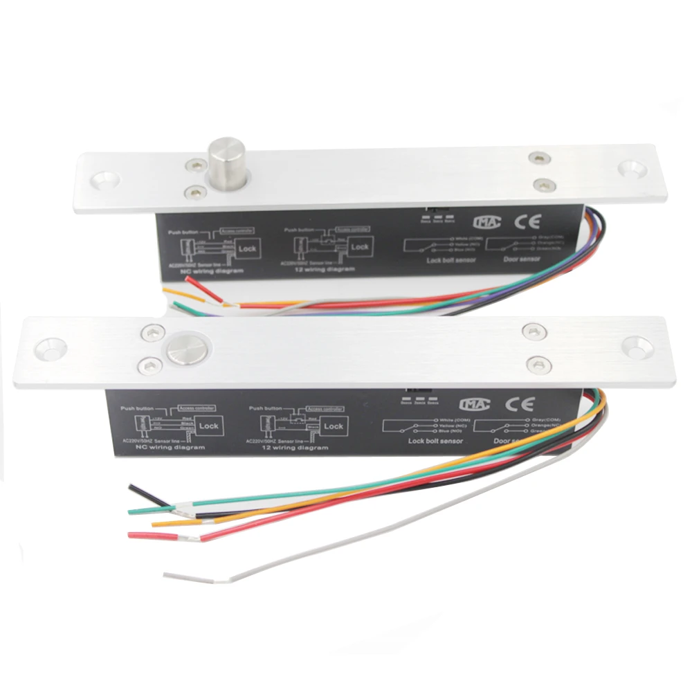
ES20 / ES20M ELECTRIC DOOR STRIKE INSTALLATION MANUAL INTRODUCTION: TECHNICAL DATA: WIRING AND POWER INPUT REQUIREMENTS: The patented ES20 series of strikes are manufactured from stainless steel and accept voltages from 12 to 36VDC. It has a 10mm lip, is pre-drilled for
Power Supply Cabinet; (2) Combo Switch, 2" x 4" Narrow 'Push to Open' & 'Push to Lock', Surface AURA(tm) Illuminated Enclosure and Sign; (2) 4-1/2" Push Plate Switch, Wheelchair & Push to Open, with Surface AURA(tm) Illuminated Enclosure and Sign; (2) 'Universal' electric strike, 12/24V AC/DC, fail safe/fail secure operation, horizontal adjustment, c/w 3 stainless …

wiring connections ..... 7 door status switch output 8 hardwired push plates with push side door-mounted sensor 8 wireless push plate with 24vdc electric strike or maglock 9 wireless push plate w/ sdc electric latch retraction 9
The strike is mounted on the body of the dryer, while the catch is mounted on the dryer door. These two parts work together to keep your dryer door closed. The catch holds the door strike to keep the door closed during the drying cycle. If the door does not latch closed, you won’t be able to start a drying cycle. If this part is malfunctioning, you may not be able to open or close your …
Capacitor start electric motors use a starting coil and a capacitor to create an advancing magnetic field in the stator (outer frame of the motor with its coils). This advancing magnetic field gives the rotor something to chase, causing the rotor to spin. (For example, put a bar magnet on top of a glass table. Bring another bar magnet up to it from under the table. Move the magnet …

Electric Door Strike Wiring Diagram - wiring diagram is a simplified normal pictorial representation of an electrical circuit. It shows the components of the circuit as simplified shapes, and the capacity and signal associates in the midst of the devices. A wiring diagram usually gives guidance not quite the relative face and promise of ...
magnetic lock or fail safe strike with button, keypad, PIR and touch sense bar or micro-switch bar wired in series N/C PIR Power Supply for fail safe strikes and magnetic locks should be DC. If this is not available you may use an AC power source an d wire inline a "Full Wave Bridge" rectifier. This will convert the AC to DC.

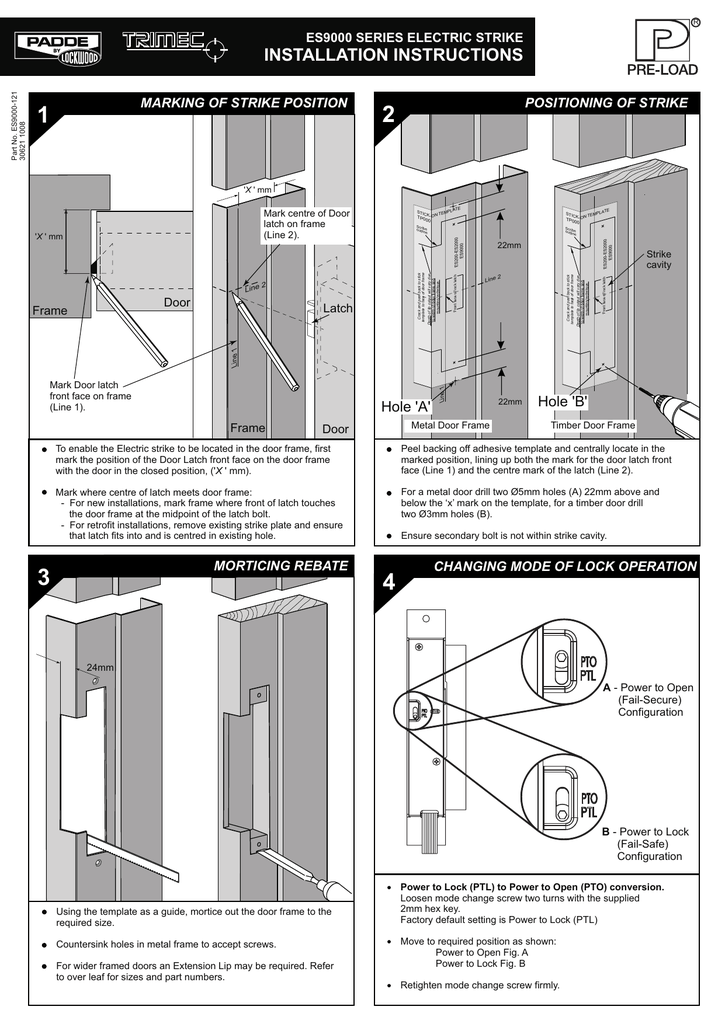
• For the metal door drill two Ø5mm holes (A) 24mm above and below the "X" mark on the template, for a timber door drill two Ø3mm holes (B). • Ensure secondary bolt is not within the strike cavity. • To enable the Electric strike to be located in the door frame, first mark the position of the Door Latch front face on the door frame
Its strength is derived from a unique keeper pin locking design, enabling the 8300 to exceed the ratings of the frame, door and locking hardware. This unique electric strike is easy to install and complies with NFPA 80-07 guidelines for retrofit into fire-rated frames. The HES 8300 accommodates latchbolts up to 5/8" throw.

All Adams Rite electric strikes have flat faces, except for the ... Latch Bolt is out of strike. Sample Wiring Diagram for Monitor Signal Operation ...
1. Check power source and make sure that the electric strike is configured to the appropriate voltage. This electric strike ships as 12V. If you need to convert the unit from 12V to 24V, see Diagram 2. 2. If your strike is supplied with the LATCHBOLT MONITOR (LBM), or LATCHBOLT STRIKE MONITOR (LBSM), see Diagrams 3 & 4 for wiring instructions. 3.

illustrated within Diagram 2. 2. If your strike is supplied with the LATCHBOLT MONITOR (LBM), or LATCHBOLT STRIKE MONITOR (LBSM), see Diagrams 3 & 4 for wiring instructions. 3. For available faceplate options, see page 4. Prepare Strike CAUTION! Before connecting any device at the installation site, verify input voltage using a multimeter.

Source: doorentrydirect.com. Size: 82.15 KB. Dimension: 800 x 565. DOWNLOAD. Wiring Diagram Pictures Detail: Name: adams rite electric strike wiring diagram - Adams Rite 7131 Electric Strike For Aluminum Stile W 4500 4700 Deadlatches Installation Instructions ES7131 0 80 0180 361 H 381. File Type: JPG.


0 Response to "39 electric door strike wiring diagram"
Post a Comment