36 torque free body diagram
Create Torque Diagram for Pulley Shaft Design Torque Diagram Step-1 . Please observe that the direction of the torque for the motor is opposite than the three machines. This is because the above FBD is showing the reaction torques and the direction of the reaction torques for the machines are opposite to that of the motor for obvious reason. The fact will be re-emphasised from the Step-2 below. Drawing free body diagrams (torque; rotational motion ... Drawing free body diagrams (torque; rotational motion) Janet1234 Mar 16, 2017 Mar 16, 2017 #1 Janet1234 1 0 Homework Statement A 500-N person stands 2.5 m from a wall against which a horizontal beam is attached. The beam is 6 m long and weighs 200N (see diagram below).
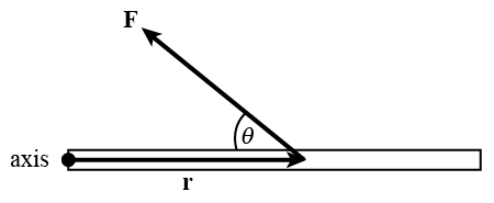
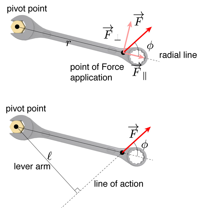
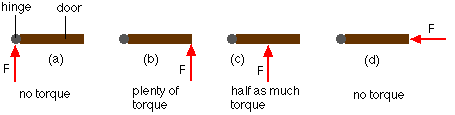
Torque; and objects in equilibrium - Boston University There are three equivalent ways to determine this torque, as shown in the diagram below. Method 1 - In method one, simply measure r from the hinge along the rod to where the force is applied, multiply by the force, and then multiply by the sine of the angle between the rod (the line you measure r along) and the force.

Torque free body diagram
1.5-3: Free body Diagrams with torque - YouTube Basic static equilibrium examples that emphasize drawing the free body diagram, choosing an axis, and evaluating torque without bothering to work out the num... Spur Gear Forces - Engineering - Vortarus Technologies LLC Looking at the free body diagrams for each gear, there is a normal force acting on each gear. The normal force acts at an angle from tangent called the pressure angle, Φ. In the case of the two gear set-up, there are opposing torques as well. For idler gears, there is no torque, but the normal forces from all gear meshes balance out. Mechanics Map - Axial Force Diagrams and Torque Diagrams To create the torque diagram for a shaft, we will use the following process. Solve for all external moments acting on the shaft. Draw out a free body diagram of the shaft horizontally, rotating the shaft if necessary, so that all torques act around the horizontal axis. Lined up below the free body diagram, draw a set of axes.
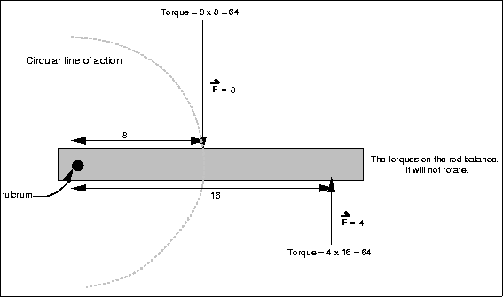
Torque free body diagram. Torque Free Body Diagrams - Torque Project Free Body Diagrams for Torque situations usually include a weight for the object experiencing the torque, various or a single support force, and any other pushes or pulls that are acting to keep... Free body diagram - Wikipedia A free body diagram consists of a diagrammatic representation of a single body or a subsystem of bodies isolated from its surroundings showing all the forces acting on it. In physics and engineering , a free body diagram ( FBD ; also called a force diagram ) [1] is a graphical illustration used to visualize the applied forces , moments , and ... Axial force, shear force, torque and bending moment diagram 2-12 Finally, we end this section with a discussion of torque diagrams. These are usually simpler than shear and bending moment diagrams, and can be illustrated with the following example. Example Draw the torque diagram for the cantilever shaft shown. Determine the maximum torque in the shaft. 5 kNm 7 kNm 12 kNm 1 m 1 m 1 m fixed end 13. 2-13 PDF Internal Loads Normal Force and Torque Diagrams Draw a free-body diagram of the shaft on either side of the cut Use a static-equilibrium equation and the following sign convention to obtain the internal torque at the section Sign Convention Using the right-hand rule, the torque and angle of twist will be positive, provided the thumb is directed outward from the shaft when the
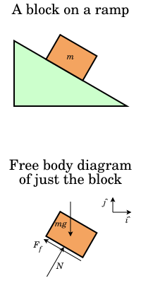
PDF Forces and Free-Body Diagrams Free-body diagrams Free-body diagrams are used to show the relative magnitude and direction of all forces acting on an object. This diagram shows four forces acting upon an object. There aren't always four forces. Problem 1 A book is at rest on a table top. Diagram the 5.7 Drawing Free-Body Diagrams | University Physics Volume 1 Figure 5.32 (a) The free-body diagram for isolated object A. (b) The free-body diagram for isolated object B. Comparing the two drawings, we see that friction acts in the opposite direction in the two figures. Because object A experiences a force that tends to pull it to the right, friction must act to the left. Because object B experiences a component of its weight that pulls it to the left ... Torques and Forces - Pitching in ... - Pitching in Baseball To rotate a body segment, an athlete applies a torque, or angular force at a joint. The amount of angular acceleration of a body segment caused by an applied torque is inversely related to that segment's moment of inertia, or the segment's resistance to rotation. For any given muscle torque, the greater the mass of a segment and the farther ... Free Body Diagram Involving Torque - Torque'n it up! Free Body Diagram Involving Torque - Torque'n it up! what does a free body diagram involving torque look like? This is a free body diagram of a yo-yo resting on a table. The force of gravity acting on the yo-yo (green arrow) is pulling downward on the yo-yo as it would on any object in ideal circumstances.
RE: Shaft Mounted Gearbox Free Body Diagram - Mechanical ... Both free body diagrams are incorrect. 1)The shaft should be in equilibrium so you must have out of plane forces and torques to match the values you have. In addition you are missing the force of the couple which is 200nm/.14m=1428n upward on the shaft. 2) The bracket should have a shear force at the mount equal and opposite the vertical force, 1428n Free-body diagrams and torque - Physics Forums The crate has length 1.25 m and height 0.50 m, and its center of gravity is at its center. The stairs make a 45.0 angle with respect to the floor. The crate also is carried at an 45.0 angle , so that its bottom side is parallel to the slope of the stairs . The force each person applies is vertical. Find the force that each person contributes with. Forces and Torques in Muscles and Joints | Physics Figure 2. (a) good posture places the upper body's cg over the pivots in the hips, eliminating the need for muscle action to balance the body. (b) Poor posture requires exertion by the back muscles to counteract the clockwise torque produced around the pivot by the upper body's weight. How to Draw a Torque Diagram Without Equations - YouTube In this video, we solve a torque diagram without having to use equations. By simply looking at the external loadings, we can easily draw the internal torque...

Review Questions
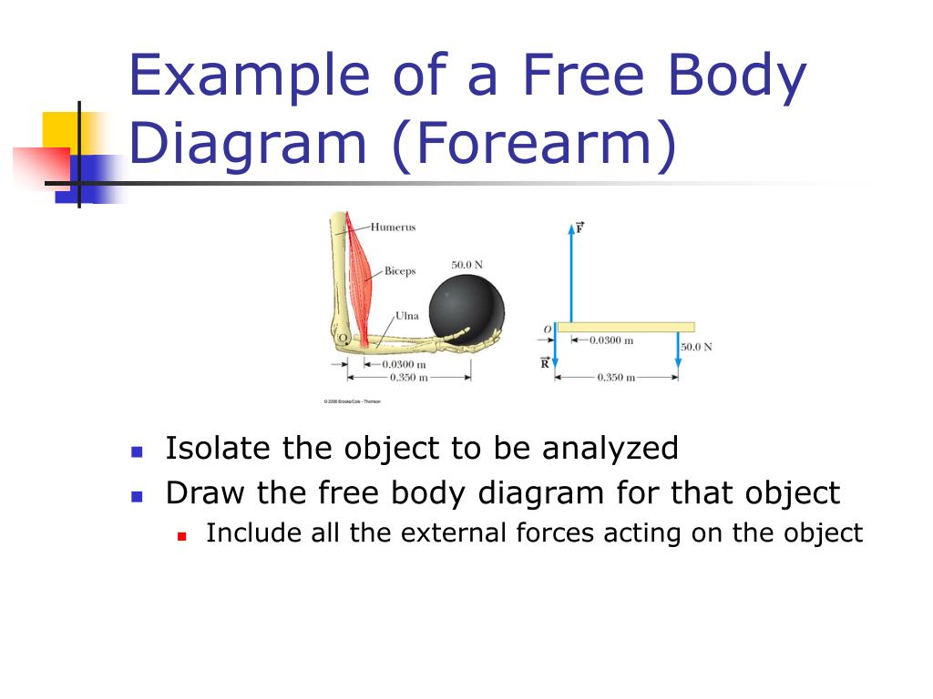
PDF Modeling Mechanical Systems - California State University ... •Draw a free body diagram, showing all forces and their directions •Write equation of motion and derive transfer function of response x to input u chp3 15. Example 2: Mechanical System chp3 16. Example 3: Two-Mass System •Derive the equation of motion for x 2 as a function of F a. The indicated damping is
Torques and Static Equilibrium
Free Body Diagrams | Representations | Videos | STEM ... A free body diagram is not likely to shed much light on the problem. This problem involves rotation and torque. Free body diagrams work best with linear motion. Even though force is involved, a free body diagram may not help. However, a more sophisticated diagram may be of assistance.
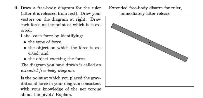
SOLVED:Draw free-body diagram for the ruler (after it is ...
Introduction: A free body diagram is a picture of the forces which act on an object and is the first (and perhaps the most important) step in solving force problems. Purpose: The purpose of the free body diagram (FBD) is to help you identify and analyze the forces that act on a particular object or body.
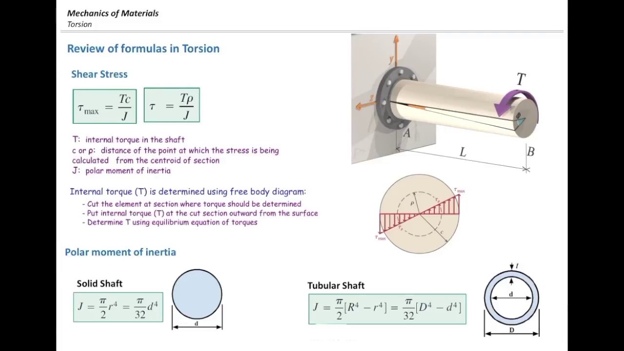
Torsional stress part2, Free body diagram and examples
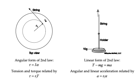
PDF Torque Torque and Rotational Inertia - Boston University Draw a free-body diagram for a horizontal rod that is hinged at one end. The rod is held horizontal by an upward force applied by a spring scale ¼ of the way along the rod. Find the reading on the scale (F. S) and the hinge force (F. H) in terms of mg, the weight of the rod if the rod is at equilibrium. Let . F. H. be the hinge force, and we decompose it into

An unusual yoyo is constructed from a hollow sphere of mass M ...
Force Calculations Free Body Diagrams. The first step is to draw a Free Body Diagram (also called a Force Diagram) Free Body Diagram: A sketch where a body is cut free from the world except for the forces acting on it. In the bridge example the free body diagram for the top of the tower is: Free Body Diagram. It helps us to think clearly about the forces acting on the body.
Free body diagram - Wikipedia
Solved A) Draw a free-body diagram. Show the torque ... Draw a free-body diagram. Show the torque reactions at supports A and C in the correct direction for resisting the applied torque, T. From your free-body diagram, write the equilibrium equation for the torques. Express the torsional equation of equilibrium for the shaft in terms of TA, and TC. B)
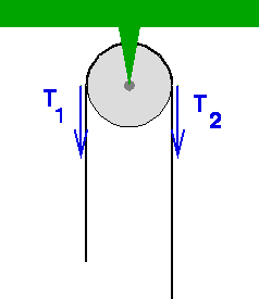
free body diagram for pulley
Basic Biomechanics: Moment Arm & Torque To calculate force you must first draw a detailed free-body diagram of the force system, including the all force components. Then torque can be calculated using on of the following formulas: Torque =Lever Arm x Fy (or Force sin ( )) Torque = Force (Fm) x Moment Arm
Phys - Lecture on torque
Brake Torque - an overview | ScienceDirect Topics If we call the vehicle stability control and the determined control torque the upper controller layer, the lower layer will adjust the longitudinal tire slip to exert the tire's largest longitudinal brake force. According to the free-body diagram of the wheel presented in Fig. 2.26, one can write (2.1);

Moment or Torque
PDF Fundamentals of Vehicle Dynamics - IIT Hyderabad Free Body Diagram 1. Vehicle fixed co-ordinate system: It is defined with reference to a right-hand orthogonal coordinate system which originates at CG and travels with the vehicle x - forward y- lateral z- downward p- roll velocity q- pitch velocity R - yaw velocity 1. Earth fixed co-ordinate system: Vehicle altitude and trajectory
College Physics
PDF Recitation 4 Notes: Torque and Angular Momentum, Pendulum ... The free body diagram depicting the torques on the body is shown below. Note the directions of the unit vectors rˆ and θˆ
PPT - Rotational Motion and Torque PowerPoint Presentation ...
Free body diagram (FBD) showing various torque components ... Download scientific diagram | Free body diagram (FBD) showing various torque components acting on the shaft. from publication: Active control of the tip vortex: An experimental investigation on ...
Solved 1. Draw an extended free body diagram for the setup ...
Mechanics Map - Axial Force Diagrams and Torque Diagrams To create the torque diagram for a shaft, we will use the following process. Solve for all external moments acting on the shaft. Draw out a free body diagram of the shaft horizontally, rotating the shaft if necessary, so that all torques act around the horizontal axis. Lined up below the free body diagram, draw a set of axes.
Torques and Static Equilibrium
Spur Gear Forces - Engineering - Vortarus Technologies LLC Looking at the free body diagrams for each gear, there is a normal force acting on each gear. The normal force acts at an angle from tangent called the pressure angle, Φ. In the case of the two gear set-up, there are opposing torques as well. For idler gears, there is no torque, but the normal forces from all gear meshes balance out.

How to Calculate the Net Torque
1.5-3: Free body Diagrams with torque - YouTube Basic static equilibrium examples that emphasize drawing the free body diagram, choosing an axis, and evaluating torque without bothering to work out the num...
12.2 Examples of Static Equilibrium | University Physics Volume 1
Mechanics Map - Axial Force Diagrams and Torque Diagrams

In a free-body diagram, should surface friction (traction) go ...

Rotation. - ppt download
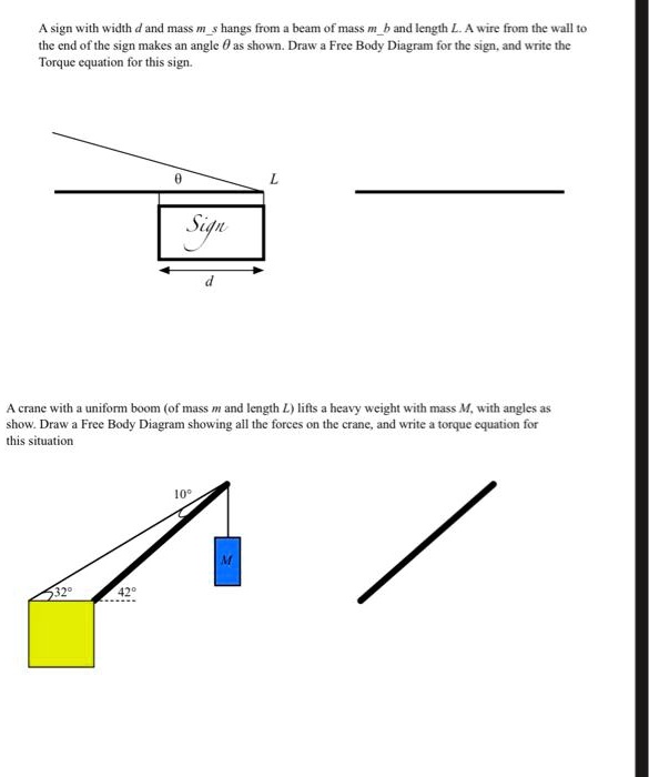
SOLVED:Asign wilh wichh _ and mas> m hangs from beam Ol miS ...
Proper free-body diagram for a shaft experiencing multiple ...

A free-body diagram that is typical of what is found in ...

Torque Free Body Diagrams - Torque Project
Basic Mechanics

Nov 3 homework

Extended Free Body Diagrams

Free body diagram - Wikipedia
Static Equilibrium Chapter 8 Questions ??? Conditions for ...
![183_notes:torquediagram [Projects & Practices in Physics]](https://msuperl.org/wikis/pcubed/lib/exe/fetch.php?w=400&tok=19bb88&media=183_notes:week12_torquediagrams2.png)
183_notes:torquediagram [Projects & Practices in Physics]

Solved C. Torque and angular acceleration. 1. Draw an | Chegg.com

Free Body Diagram For Torque | Passing the Torque
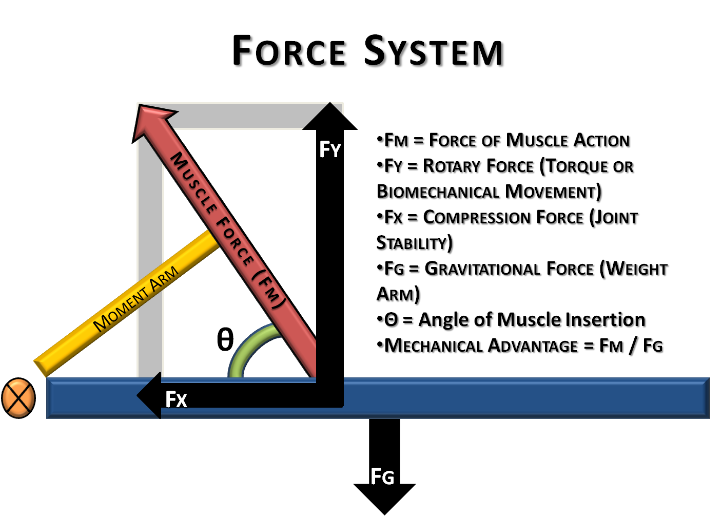
Basic Biomechanics: Moment Arm & Torque
static equilibrium

MecMovies 4.0 : M6.7: Multiple torques

Lead Screw with Friction - MATLAB & Simulink
Torque; and objects in equilibrium

Gears and Systems with both Rotation and Translation
0 Response to "36 torque free body diagram"
Post a Comment