38 consider the circuit diagram depicted in the figure.
AC Capacitance and Capacitive Reactance in AC Circuit Consider the series RC circuit below where an ohmic resistance, R is connected in series with a pure capacitance, C. In the vector diagram above, line OB represents the horizontal current reference and line OA is the voltage across the resistive component which is in-phase with the current. Physics Tutorial: Circuit Symbols and Circuit Diagrams Electric Circuits - Lesson 4 - Circuit Connections. Circuit Symbols and Circuit Diagrams. As an illustration of the use of electrical symbols in schematic diagrams, consider the following two The conventional current in the external circuit is the direction that a positive charge would move.
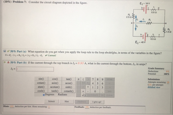
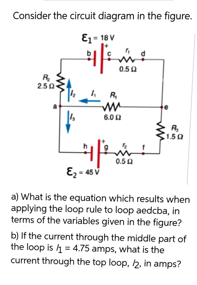
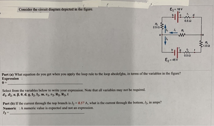
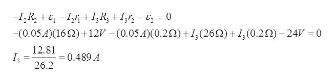
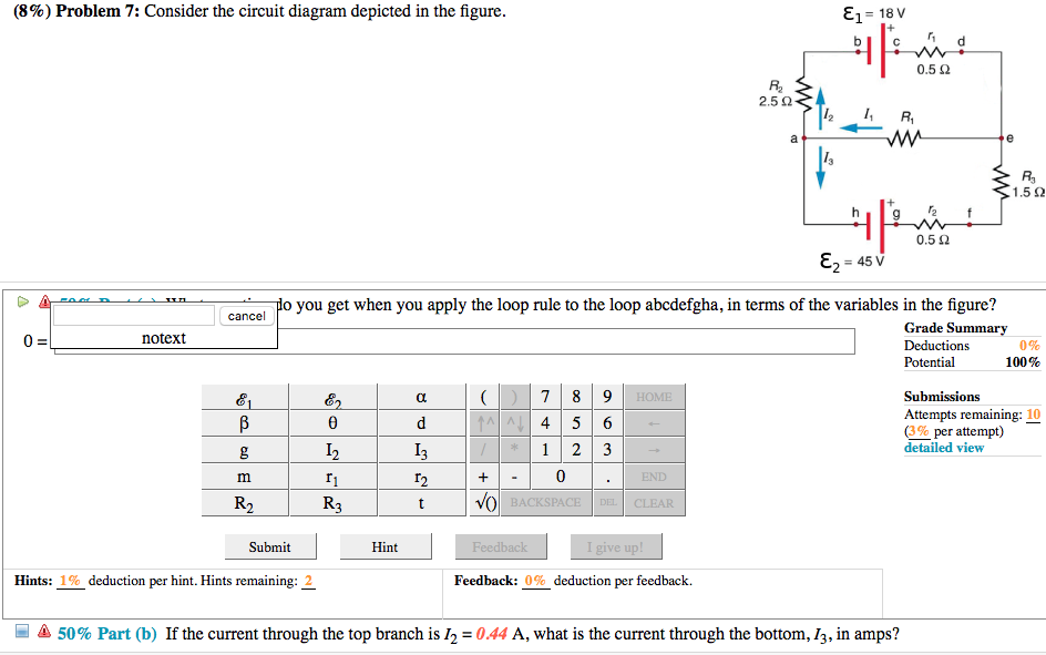
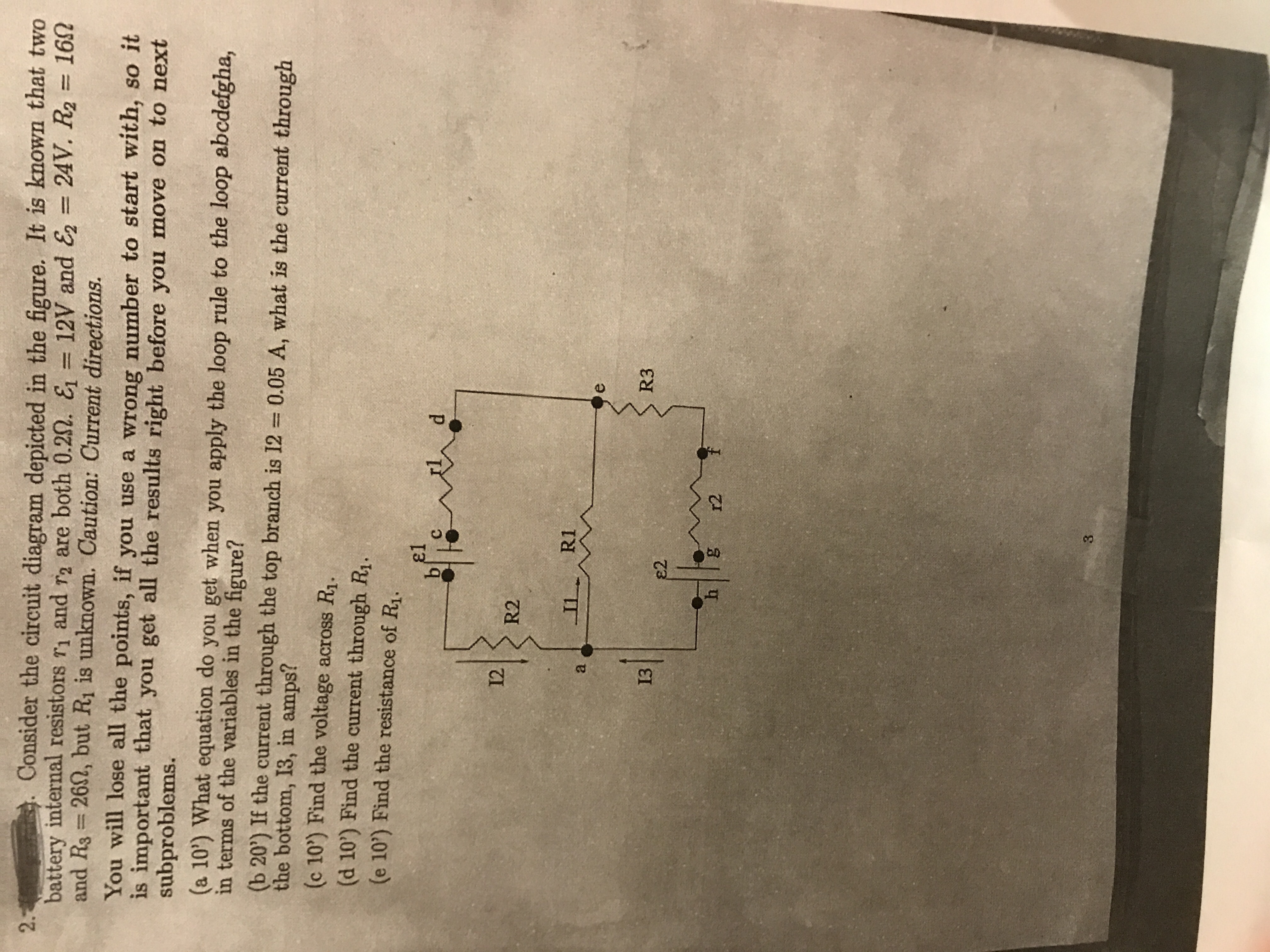
Solved Consider the circuit diagram depicted in the figure. Transcribed image text : Consider the circuit diagram depicted in the figure. What equation do you get when you apply the loop rule to the loop abcdefgha? If the current through the top branch is I_2 = 0.49 A. what is the current through the bottom, I_3, in amps?

Consider the circuit diagram depicted in the figure.
Consider the circuit shown in the figure below... | Physics Forums circuit diagram ??? I think I see what you were trying to write in the previous post now and that actually is correct, you just didn't put parenthesis in the right place (you should check out how to use LaTeX on this board so we don't misinterpret what you're typing like I just did up there). Consider The Circuit Diagram Depicted In The Figure Consider a diagram describing a parallel ac circuit containing a resistor a capacitor and an inductor. For the action depicted in the figure figure 2 indicate the direction of the induced current in the loop clockwise counterclockwise or zero when seen from the right of the loop. PDF Control system theory | List of Figures A simple electrical circuit is illustrated in Figure 1.6. Using Kircho's volt-age and current laws we may obtain a state space model in which the current In the previous examples we began with a physical description of the system to be controlled, and through physical laws obtained a state space model of...
Consider the circuit diagram depicted in the figure.. Resistors in Series and Parallel | Physics Most circuits have more than one component, called a resistor that limits the flow of charge in the circuit. A measure of this limit on charge flow is called resistance. These energies must be equal, because there is no other source and no other destination for energy in the circuit. Simple Circuits | Brilliant Math & Science Wiki Circuits are driven by flows. Flows are ubiquitous in nature and are often the result of spatial Consider the diagram below, depicting a set of resistors in parallel, connected to a battery of ri in the loop (yellow dot in the above figure), then traveling around the loop, thus changing the potential... Nyquist Diagram - an overview | ScienceDirect Topics The Nyquist diagram and Cole-Cole diagram are common terms for graphic presentations in the complex ( z ) plane. The circuit and its component values were selected on purpose to clearly show the relationship between Consider a linear system operating in steady state at an operating point... MasteringPhysics: Print View with Answers Consider this phasor diagram: The diagram describes a circuit that contains two elements connected in parallel to an AC source. Part B When a lamp is connected to a wall plug, the resulting circuit can be represented by a simplified AC circuit, as shown in the figure.
Control Systems - Block Diagrams Control Systems - Block Diagrams, Block diagrams consist of a single block or a combination of blocks. Let us consider the block diagram of a closed loop control system as shown in the following figure to identify these elements. Consider a series of RLC circuit as shown in the following figure. Engineering circuit analysis ENGINEERING CIRCUIT ANALYSIS 28 CHAPTER 2 BASIC COMPONENTS AND ELECTRIC CIRCUITS we define an open circuit as an infinite resistance. a negative value for absorbed power. EXERCISES 29. Determine the power supplied by the leftmost element in the circuit of Fig. PDF Electrical Networks and Algebraic Graph Theory Consider the DC circuit shown in Figure 4(a), which con-sists of an ideal DC voltage supply providing power to a load through a resistance r. Classic methods in the study of electric circuits are the contraction of a series of resistive circuit elements and the Y-∆ transformation; these methods date... Parallel Circuit Definition | Parallel Circuit... | Electrical Academia Fig.1: Circuit Diagram for Parallel Connected Resistors. Consider the circuit in figure 5, which has four resistors connected in parallel. Use the current divider equation to determine the branch currents in the circuit of figure 5. The component values are
Recent Advances in the Modeling of Transmission Lines Loaded with... -circuit model (unit cell) of the considered line.) In the last case, wave propagation is allowed, and it is backward (i.e., the phase and group velocities The typical topology of an SRR-loaded metamaterial transmission line, based on CPW technology, is depicted in Figure 1(a). The line is loaded with an... PDF Electrical Engineering Laboratory II | Lab 6 - Circuit Resonance Instead, describe the circuit as a whole (preferably with diagram), and explain how it works. Your description should take the form of a narrative, and include information not present in the manual, such as descriptions of what AC voltage and current waveforms are further depicted in a number of ways. PDF MasteringPhysics: Assignment Print View Consider this phasor diagram: The diagram describes a circuit that contains two elements connected in Part A At the moment depicted in the diagram, which of the following statements is true? The current in the circuit has amplitude , as indicated in the figure. Which of the following choices gives... For the circuit shown in the figure, calculate (a) the current in the... For the circuit shown in the figure, calculate (a) the current in the 2.00-Ω resistor and (b) the potential difference between points a and b, ΔV = Vb - Va.
10) Problem 1 Consider the circuit diagram depicted in the ...
PDF Electrons and Holes Figure 1-3b shows that the silicon wafers are usually cut along the (100) plane to obtain uniformity and good device performance. A flat or a notch is cut While the bond model described in the previous section is conceptually simple, it is not complete enough for understanding semiconductor devices.
Accelerating with FlyBrainLab the discovery of the functional ...
Topology (electrical circuits) - Wikipedia For instance, the three circuits shown in figure 1.1 all look different but have identical topologies.[2]. In a circuit diagram these element-kinds are specifically drawn, each with its own unique symbol. In the field of electrical networks, there are two additional transforms that are considered to result in...
Voltage Transients in the Field Winding of Salient Pole Wound ...
Circuit Simplification Examples | Boolean Algebra | Electronics Textbook Let's consider an example circuit: As before, our first step in reducing this circuit to its simplest form must be to develop a Boolean expression from the In the above figure, a long dash symbol (—) is used to represent the series connection of resistors. Remember that parallel contacts are equivalent...
Solved (10%) Problem, 7: Consider the circuit diagram | Chegg.com
Design and Analysis of Sequential Circuits Circuit analysis begins with a circuit diagram or a black box and ends with an identification of the sequential Another tool in the design and analysis of sequential circuits is the transition table. Consider the following circuit. We want to discover what it does. Figure: Circuit to Be Analyzed.

Density of Water + Carbon Dioxide at Elevated Pressures ...
Skill Builder: Reading Circuit Diagrams - Make Circuit diagrams depict a perfect world where wires and other conductors do not interfere with one another and have no resistance of their own. Chips are single components physically, but functionally, some chips contain multiple independent components housed in the same package.

A synthetic phage λ regulatory circuit | PNAS
Answered: ENL Consider the circuit diagram… | bartleby Transcribed Image Text:Consider the circuit diagram depicted in the figure. E- 18 V 0.50 250 ww 1.50 0.50 (a) What equation do you get when you apply the loop rule to the loop abcdefgha, in terms of the variables in the figure? (b) If the current through the top branch is 037 A, what is the current...

10) Problem 1 Consider the circuit diagram depicted in the ...
PE Assignment | PDF | Field Effect Transistor | Bipolar Junction... Consider the circuit diagram in Fig.14. The two thyristor are identical and have a transient thermal impedance characteristic as shown in Table1. A power MOSFET is employed as a chopper to modulate power from a dc supply of 50 V to a resistive load. Figure 17 depicts the circuit diagram.
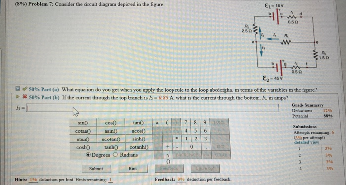
Solved (8%) Problem 7: Consider the circuit diagram depicted ...
Simple Voltage Multiplier Circuits Explored - Homemade Circuit... The following figures depict cascaded type of voltage doublers. The diagram shown below is the The simplest form of the voltage doubler circuit are a type of rectifier which takes the input in the The circuit is considered to be a modification of the Cockcroft-Walton multiplier but with the only...

Using power MOSFETs in DC motor control applications | Nexperia
How to determine the direction of current in a circuit - Quora Figure 1. Circuit diagram of a two-terminal electric network/circuit, with the positive reference polarity for the instantaneous voltage and the positive reference direction for the instantaneous current labeled, and chosen such that the passive sign convention is satisfied.
Watt-level blue light for precision spectroscopy, laser ...
A Tutorial for Beginners (Part 4)—Circuit Diagrams Using Circuitikz end{circuitikz}. This is what the diagram looks like compiled: Now let's add a voltmeter in parallel to the lamp. Therefore we need to shorten the lines either side of the lamp so that the terminals appear at our line joins, and then we need to fill in the gaps

Sustainable operation of geothermal power plants: why ...
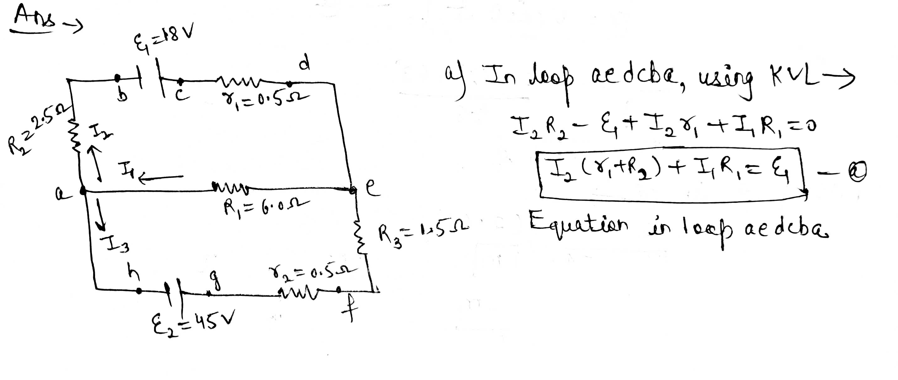
(10) Problem 1 Consider the circuit diagram depicted in the figure..... 1.592 0.50 45 V A 50% Part (a) What equation do you get when you apply the loop rule to the loop abcdefgha, in terms of the variables in the figure? > A 50% Part (b) If the current through the top branch is 12 = 0.83 A, what is the (10%) Problem 5: A Wheatstone bridge is a null measurement.
Answered: Consider the circuit diagram in the… | bartleby
PDF We shall examine three special cases of driven circuits Before examining the driven RLC circuit, let's first consider the simple cases where only one The time dependence of the current and the voltage across the resistor is depicted in Figure 12.2.2(a). The current and voltage plots and the corresponding phasor diagram are shown in the Figure 12.2.4...
Answered: Consider the circuit diagram in the… | bartleby
PDF Control system theory | List of Figures A simple electrical circuit is illustrated in Figure 1.6. Using Kircho's volt-age and current laws we may obtain a state space model in which the current In the previous examples we began with a physical description of the system to be controlled, and through physical laws obtained a state space model of...

A Novel and Inexpensive Approach for Force Sensing Based on ...
Consider The Circuit Diagram Depicted In The Figure Consider a diagram describing a parallel ac circuit containing a resistor a capacitor and an inductor. For the action depicted in the figure figure 2 indicate the direction of the induced current in the loop clockwise counterclockwise or zero when seen from the right of the loop.
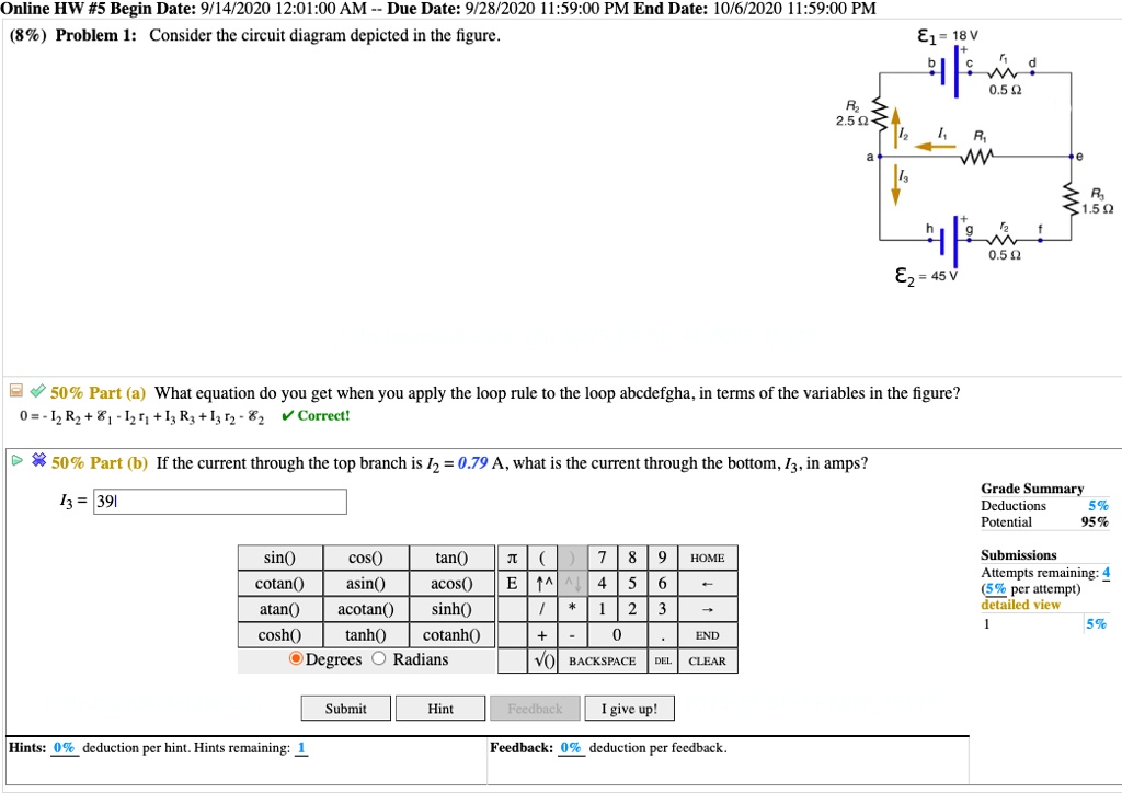
SOLVED:Online HW #5 Begin Date: 9/14/2020 12.01.00 AM Due ...
Consider the circuit shown in the figure below... | Physics Forums circuit diagram ??? I think I see what you were trying to write in the previous post now and that actually is correct, you just didn't put parenthesis in the right place (you should check out how to use LaTeX on this board so we don't misinterpret what you're typing like I just did up there).
Frontiers | Space High-Voltage Power Module | Energy Research
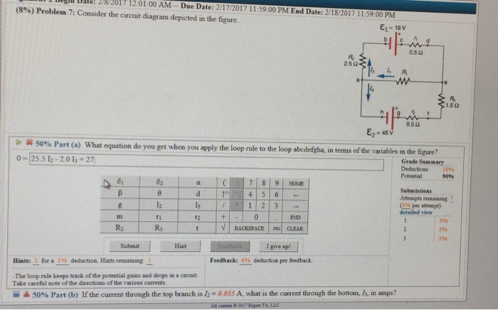
Solved L 2017 12:01:00 AM Due Date: 2/17/2017 11:59:00 PM ...
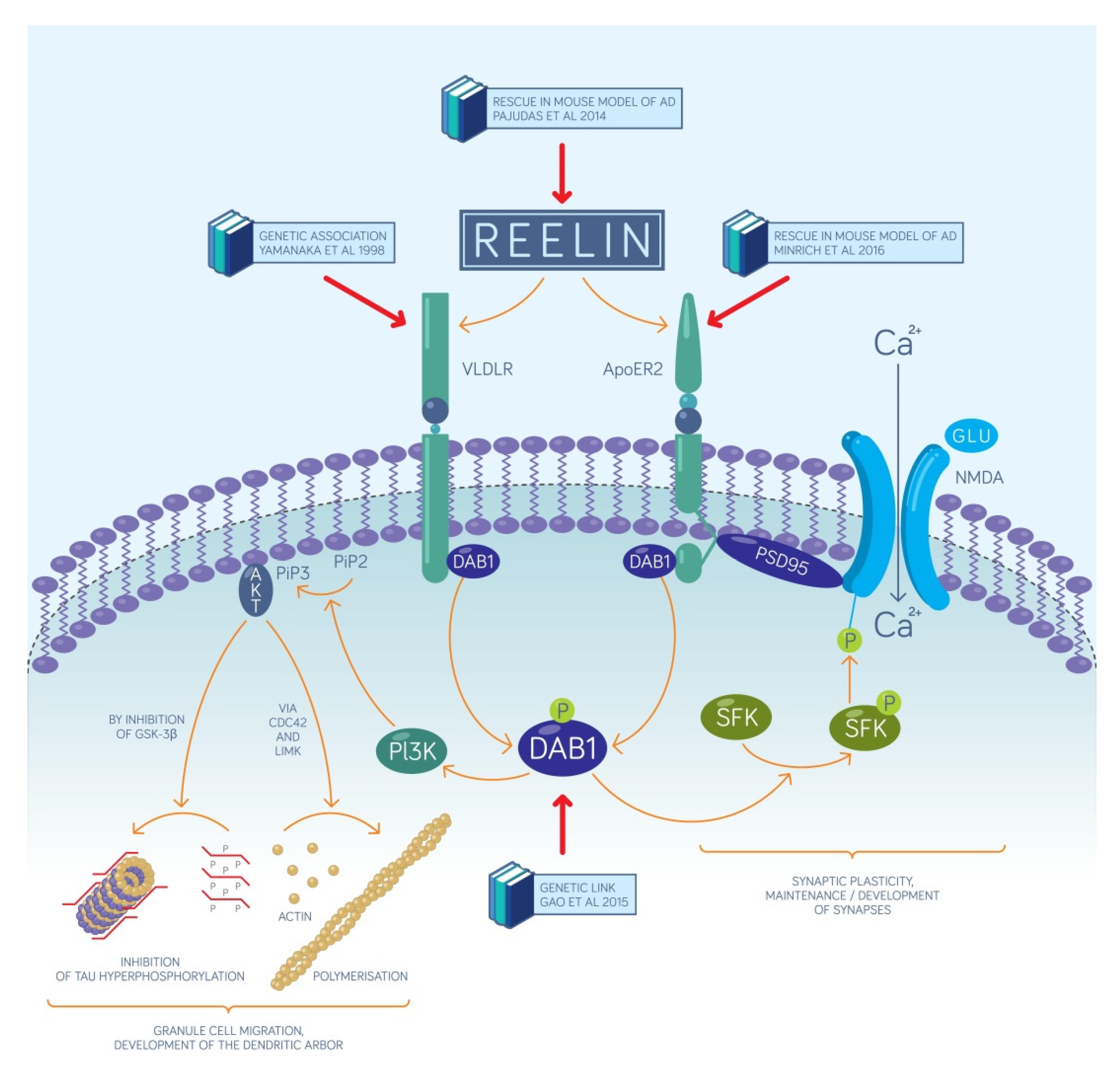
IJMS | Free Full-Text | Relevance of a Novel Circuit-Level ...
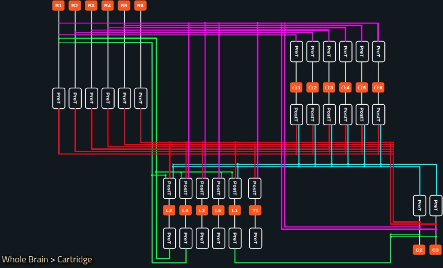
Accelerating with FlyBrainLab the discovery of the functional ...
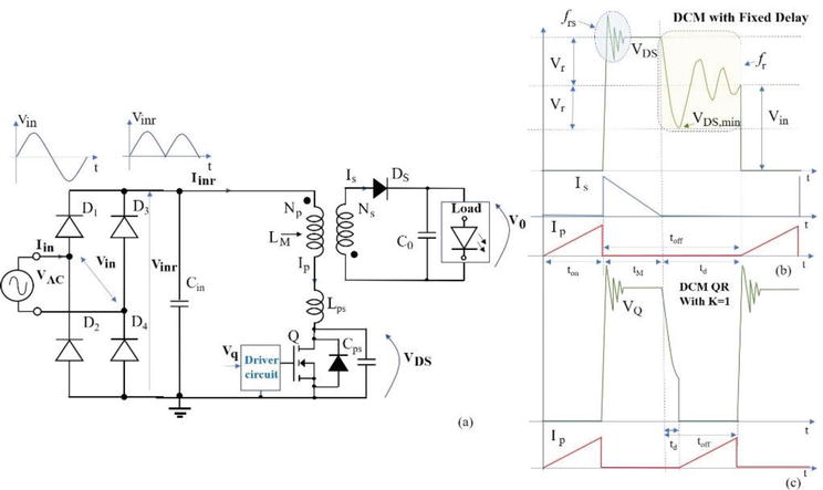
Passive and Active Topologies Investigation for LED Driver ...
Solved Consider the circuit diagram depicted in the figure ...
Answered: Consider the circuit diagram depicted… | bartleby
Solved (8%) Problem 7: Consider the circuit diagram depicted ...

Refer to the circuit diagram depicted in Figure 1 below ...
Answered: Consider the circuit diagram depicted… | bartleby

Gilbert Cell - an overview | ScienceDirect Topics

Consider the circuit diagram depicted in the figure
Model-based parametric study of frontostriatal abnormalities ...
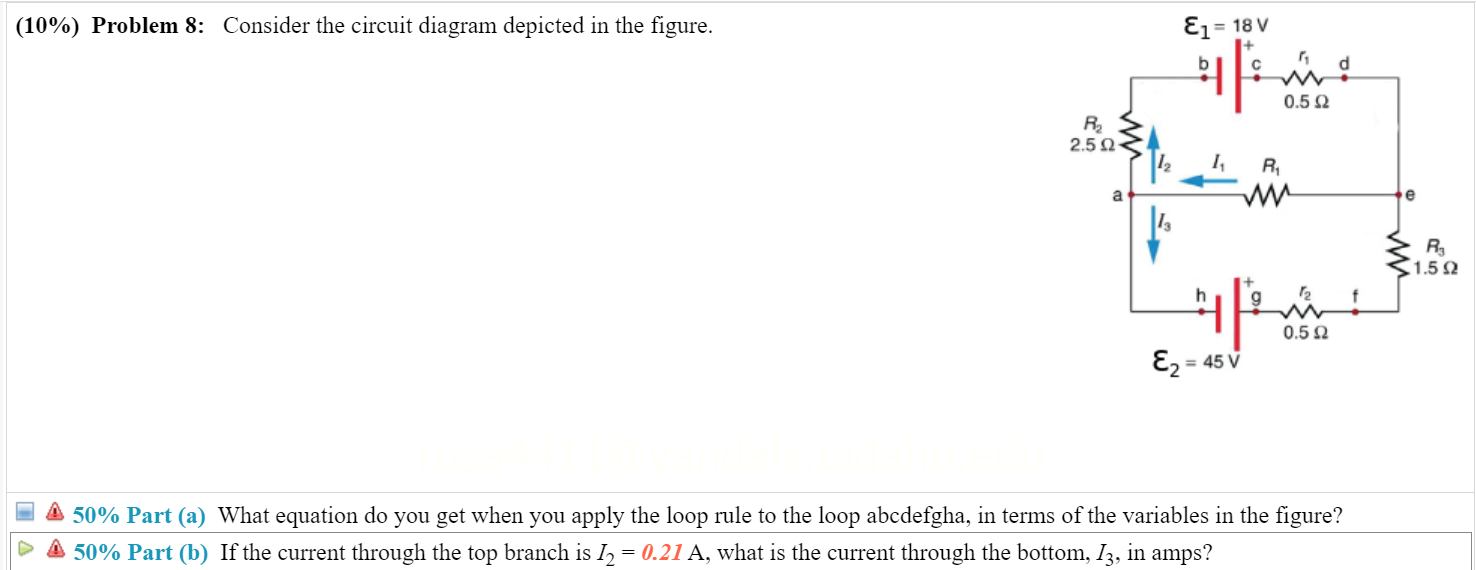
Solved (10%) Problem 8: Consider the circuit diagram | Chegg.com
Electronics | Free Full-Text | Selection and Optimization of ...
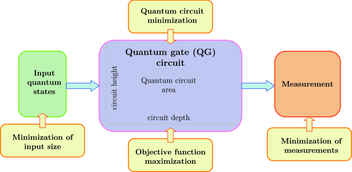
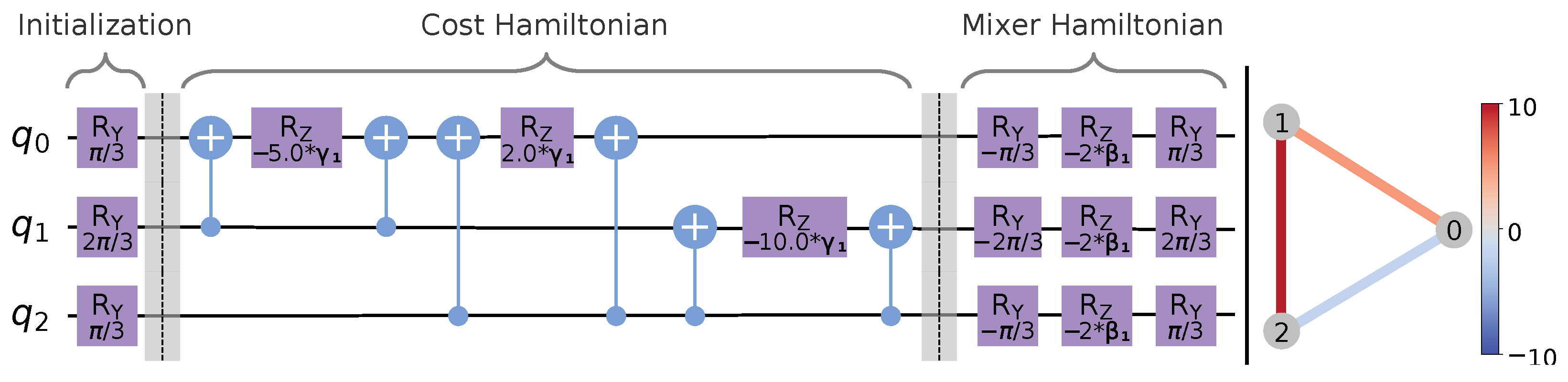
Quantum circuit design for objective function maximization in ...

Consider the circuit diagram depicted in the figure. (a) What ...

Femtosecond laser micromachining for integrated quantum photonics

Controlling electrochemical growth of metallic zinc ...
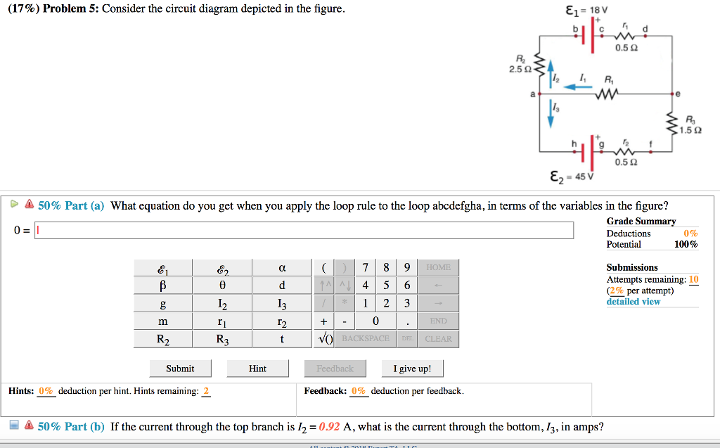
Solved (17%) Problem 5: Consider the circuit diagram | Chegg.com

10) Problem 1 Consider the circuit diagram depicted in the ...

RF Signal Chain Discourse—Part2: Essential Building Blocks ...
13%) Problem 7: Consider the circuit diagram depicted in the ...
0 Response to "38 consider the circuit diagram depicted in the figure."
Post a Comment