36 gecko g540 wiring diagram
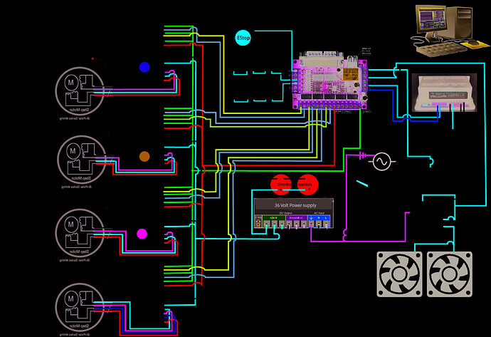
Gecko G540 Wiring Diagram Database - got2bwireless.com Gecko G540 Wiring Diagram from tse3.mm.bing.net Print the electrical wiring diagram off and use highlighters in order to trace the routine. When you make use of your finger or perhaps stick to the circuit along with your eyes, it may be easy to mistrace the circuit. One trick that We 2 to print out exactly the same wiring diagram off twice. Gecko G540 Based Stepper Controller Wiring Diagram Gecko G540 Based Stepper Controller Wiring Diagram. I have produced a wiring diagram for a 4-axis stepper controller based around the G540 drive. It should be a help to those wanting to to put their own controller together. The diagram can be found towards the bottom right of the following page.
Stepper Motor Wiring & Connections | Wiring Diagrams ... Section 5: Motor Connections. Stepper motors have four, six, or eight wires; older motors may have five wires, but they will not be covered here. Four-wire motors are the simplest to connect and offer no connection options. Simply connect one winding to the terminals labeled "Phase A" and "Phase /A" and connect the other winding to the ...
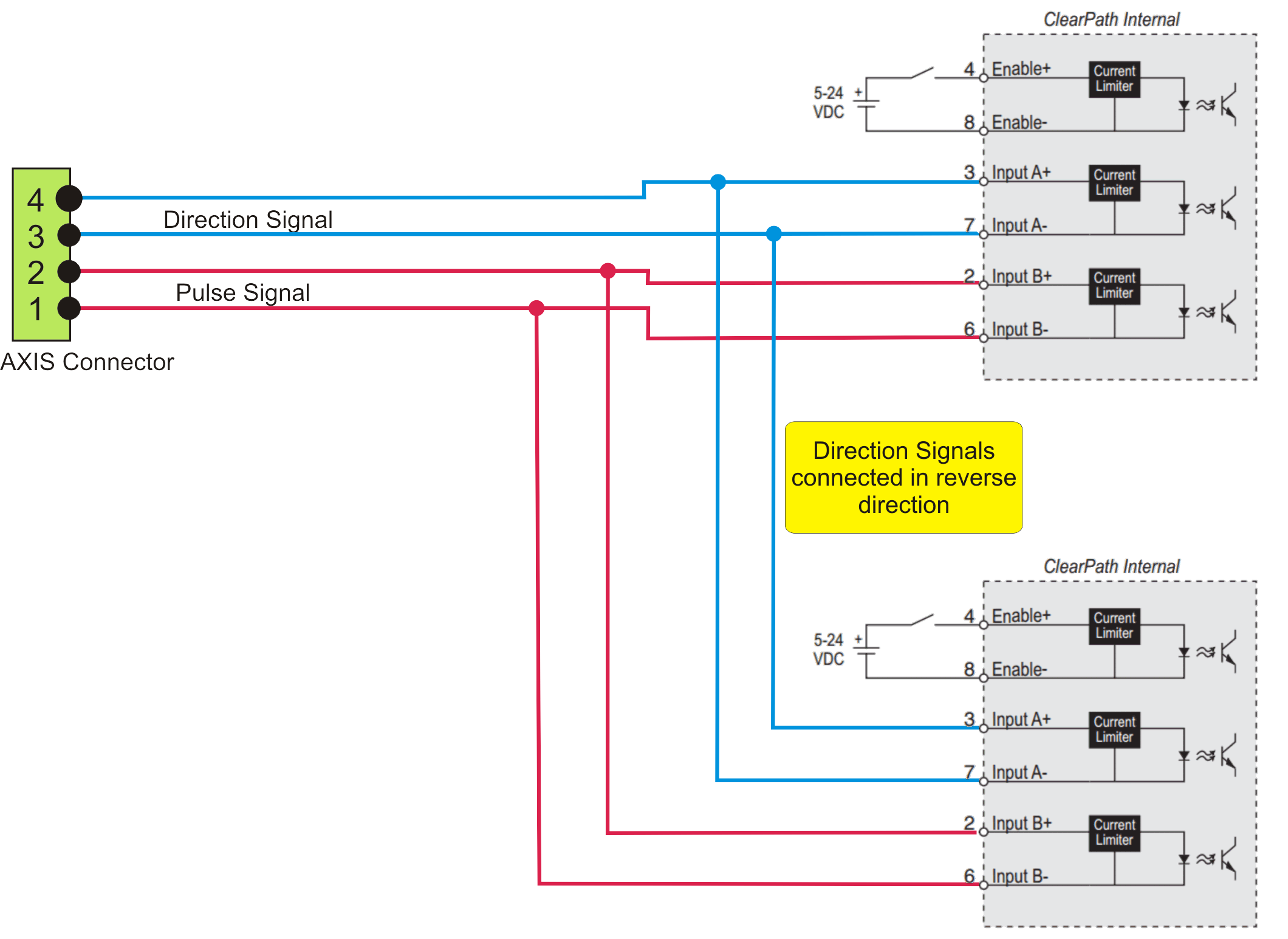
Gecko g540 wiring diagram
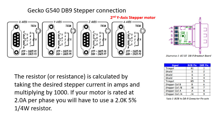
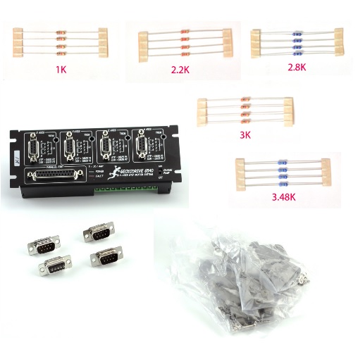
PDF G540 User Manual - Chicago Lathe G540 4-AXIS STEP MOTOR CONTROL REVISION: 8 _____ Date Modified: March 5, 2012 Page 4 of 10 multiplying by 1000. If your motor is rated at 2.8A per phase you will have to use a 2.8K 5% 1/4W resistor. If your motor is rated at 3.5A or above you can safely not use a current set resistor; however, your G540 will not go into current standby mode ... CNC machine DIY plans and build instructions - Craftsmanspace The machine uses chinese linear rails and ballscrews from ebay. With the 1.8Nm stepper motors I use with geckodrive g540 it achieves 10m/min rapids and 5m/min feedrates. The working area is about 110cm x 60cm x 10cm. Expected cost to build a machine like this from scratch is 1000-1300 euros. It also took me over 80 hours to build. - CNC Router ... PDF G540 INITIAL SETUP GUIDE - Geckodrive Inc. of the diagram concerning that is shown below, with the ENABLE hooked up to an emergency stop switch. If this is not done, then the G540 will not come out of FAULT mode. Step 2: Make sure your parallel port is set to EPP mode. Your parallel port must be set to EPP mode in BIOS for the parallel port to work correctly with the G540.
Gecko g540 wiring diagram. Gecko G540 Wiring - diagramweb.net DOWNLOAD Gecko G540 Wiring. Close DOWNLOAD. Gecko G540 Wiring. ... Drum Switch wiring for Dummies · Wiring diagram for Gecko g and.Gecko Diver G 4 Axis Driver, Current New Version, one year manufacture warranty. The G is a complete 4-axis system which plugs directly into your computer via the parallel port and to your motor. Gecko G540 Switch Installation Complete Overview.. - YouTube This video explains the wiring diagram, required for installing limit/home switches in your G540 based CNC controller. The process covered in this video incl... Web Development Services - Web Development Company | Logo ... Your business website represents your brand. Therefore, its functional efficiency is important for your market reputation. Our web development services helps you to develop websites that comply with current industry standards, providing a seamless experience to your end-users.. Our web developers create high-performing websites using state-of-art website development practices. N. Korea's parliamentary session | Yonhap News Agency Sep 30, 2021 · N. Korea's parliamentary session. This photo, released by North Korea's official Korean Central News Agency on Sept. 30, 2021, shows Kim Yo-jong, North Korean leader Kim Jong-un's sister and currently vice department director of the ruling Workers' Party's Central Committee, who was elected as a member of the State Affairs Commission, the country's highest decision-making body, during the ...
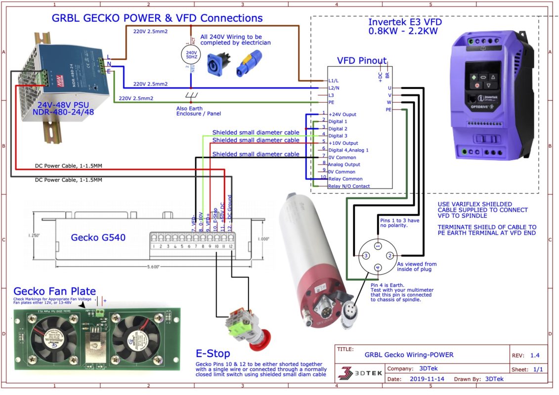
Gecko G540 Based Stepper Controller Wiring Diagram Re: Gecko G540 Based Stepper Controller Wiring Diagram. « Reply #12 on: January 17, 2010, 12:34:30 AM ». Hi, I've done Revision 8 of the schematic. It shows a bit more information on. connecting the G540 to a VFD. The schematic can be found at the bottom of the CNC Controller Kit page. Gecko G540 Wiring - Wiring Diagram Pictures - schematron.org Gecko G540 Wiring. Harbor freight CNC conversion. GECKO G Setup Power, E-Stop, & Cooling The Gecko G requires V . 3Dtek will generally sell the Geckos with a Meanwell W 24 or 48V din rail. Hi. Purchased the G after unsuccessfully trying to cobble together a system using some other drives. G540 Spindle and Relay Wiring Diagram - The Blog G540 Spindle and Relay Wiring Diagram Posted on September 16, 2017 February 17, 2019 by Tyler @ Design Concepts I've had the hardest time trying to find a simple wiring diagram for the Gecko G540 controller that includes how to wire up spindle and relay control. Stepper Drive Wiring for 80VDC 7A Rated ... - Geckodrive This wiring diagram applies to all 80VDC 7A rated stepper drives including the G201, G201X, G202, G203V, G210, G210X, G212, G213V, GM215 and G214. Please note that the G201X, G210X, G214, and GM215 have onboard DIP switches for setting current, and no current set resistor is required. Consult the manual for your motor control for the most ...
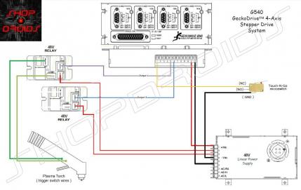
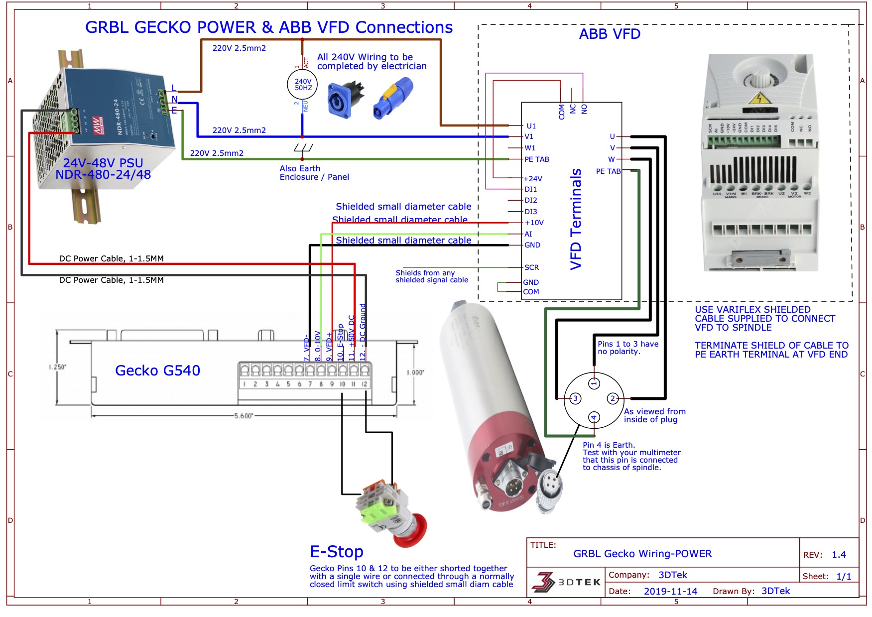
Gecko G540 Relay Configuration & Wiring Diagram Explained. This video covers the installation of relays in your G540 motion control system. I cover the how, and why, and will be offering a complete kit to make this a... Masso GEN2 Wiring Diagrams - CNC Routers | 3DTEK GECKO G540 MOTOR WIRING. Download Schematics For Print . Gecko, Cooler and Motor Connector Mounting. The Gecko G540 and Cooler are mounted and separated using standoffs. The Cooler plate sits below the G540 on its shorter standoffs, with the fan's sticker side facing the bottom of the G540; The Control Card is pressed onto the top of the G540 ... GRBL + Gecko G540 Combo Wiring Diagrams - CNC Routers | 3DTEK Gecko, Cooler and controller Mounting The Gecko G540 and Cooler are mounted and separated using standoffs. The Cooler plate sits below the G540 on its shorter standoffs, with the fan's sticker side facing the bottom of the G540 The Control Card is pressed onto the top of the G540 and holds its self in place firmly. PDF CC-01 G540 Stepper Controller Kit Wiring Revision 8.4 MB ... G540 GeckoDrive™ 4-Axis Stepper Drive System Homann Designs Parts Used-----1 x G540 GeckoDrive 4-Axis Stepper drive 3 X SM-03 387 Oz-in Stepper Motors 1 x PS-01 48V 7.3A linear Power Supply 2 x RL-04 48V coil, 20A SPST Relays 1 x SW-01 Latching Estop Switch 1 x SW-06 IEC Plug/Switch/Fuse 1 x CB-10 IEC Female Socket 1 x SW-12 Mini Rocker switch
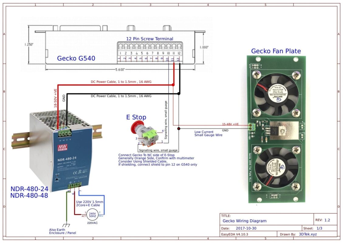
Gecko Wiring Diagrams - CNC Routers | 3DTEK Gecko Wiring Diagrams. Posted on 01/03/201912/04/2020 by 3DTek. 01. Mar. Below are the wiring diagrams for 3Dtek specific Gecko G540 Applications. These may or may not be useful for other Gecko use cases. Please contact 3DTek for any assistance wiring up or configuring these devices. Stepper Motor Connections (c) G540 Motor Connector Board Method<.
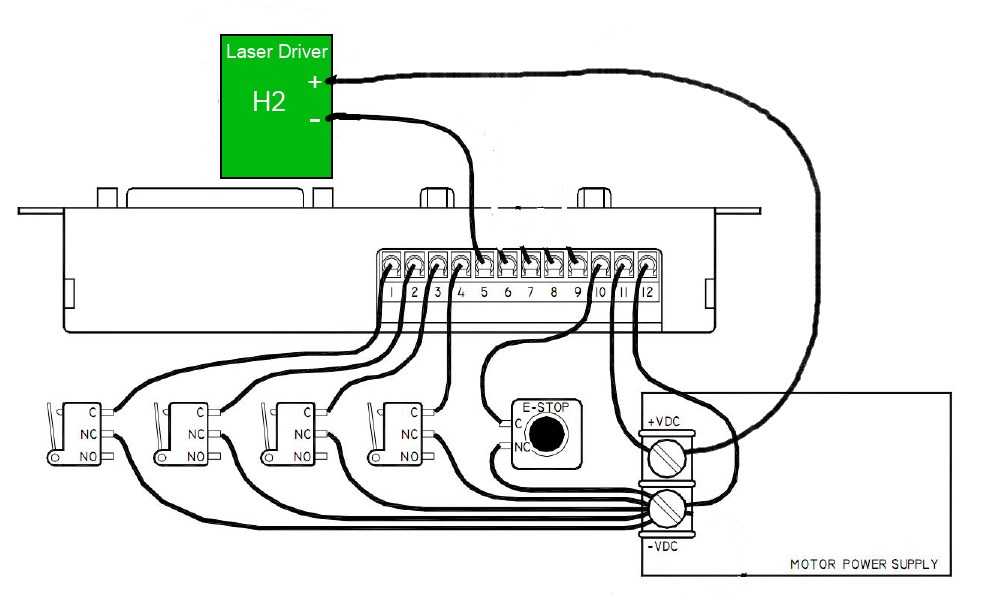
G540 Initial Setup Guide | Geckodrive | Geckodrive G540 Initial Setup Guide. This is a quick guide to setting up your G540 for the first time to eliminate any setup headaches you may have. STEP 1: DETERMINE THAT THE ENABLE PIN IS CONNECTED. The first thing you should do is to connect your ENABLE pin (Pin 10) to GND (Pin 12). The section of the diagram concerning that is shown below, with the ...
G540 Spindle and Relay Wiring Diagram | Diagram ... Oct 10, 2017 - How to wire up the Gecko G540 with VFD Spindle Control. Pinterest. Today. Explore. When autocomplete results are available use up and down arrows to review and enter to select. Touch device users, explore by touch or with swipe gestures. ... G540 Spindle and Relay Wiring Diagram. How to wire up the Gecko G540 with VFD Spindle ...
akiba-pc.watch.impress.co.jp › topics › usedpc_hotline中古パソコンのおすすめ品やセール情報を紹介 - 中古PC Hotline! 中古パソコンの最新情報をお届け。WindowsノートやゲーミングPC、Mac、iPad、リユースPC、Office付きPCなど、お買い得な中古品を多数紹介。秋葉原の ...
G540 REV-8 4 Axis Drive System Product Guide - Geckodrive The G540 is composed of four individual G250 motor controls, each of which has a designated pin outputting the smoothness adjust trimpot to the G540 motherboard. In your CNC program set the axis being adjusted to move at 2 revolutions per second and use a screwdriver to turn the trimpot in the ADJUST hole on the top of the drive.
G540 wiring diagram for dummies? :) - CNCzone Wiring diagram for Gecko g540 and cnc4pc C8 relay; 03-11-2009, 04:43 AM #2. jalessi. View Profile View Forum Posts Private Message View Gallery Uploads Member Join Date Feb 2007 Location United States Posts 4554 Downloads 1 Uploads 0. What model Keling steppers do you have?
PDF G540 INITIAL SETUP GUIDE - Geckodrive Inc. of the diagram concerning that is shown below, with the ENABLE hooked up to an emergency stop switch. If this is not done, then the G540 will not come out of FAULT mode. Step 2: Make sure your parallel port is set to EPP mode. Your parallel port must be set to EPP mode in BIOS for the parallel port to work correctly with the G540.
CNC machine DIY plans and build instructions - Craftsmanspace The machine uses chinese linear rails and ballscrews from ebay. With the 1.8Nm stepper motors I use with geckodrive g540 it achieves 10m/min rapids and 5m/min feedrates. The working area is about 110cm x 60cm x 10cm. Expected cost to build a machine like this from scratch is 1000-1300 euros. It also took me over 80 hours to build. - CNC Router ...
PDF G540 User Manual - Chicago Lathe G540 4-AXIS STEP MOTOR CONTROL REVISION: 8 _____ Date Modified: March 5, 2012 Page 4 of 10 multiplying by 1000. If your motor is rated at 2.8A per phase you will have to use a 2.8K 5% 1/4W resistor. If your motor is rated at 3.5A or above you can safely not use a current set resistor; however, your G540 will not go into current standby mode ...




![EN010_V8.pdf - [PDF Document]](https://img.dokumen.tips/img/1200x630/reader021/image/20170912/563dbad2550346aa9aa85726.png?t=1644176437)






0 Response to "36 gecko g540 wiring diagram"
Post a Comment