36 defrost termination switch wiring diagram
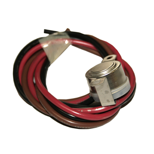
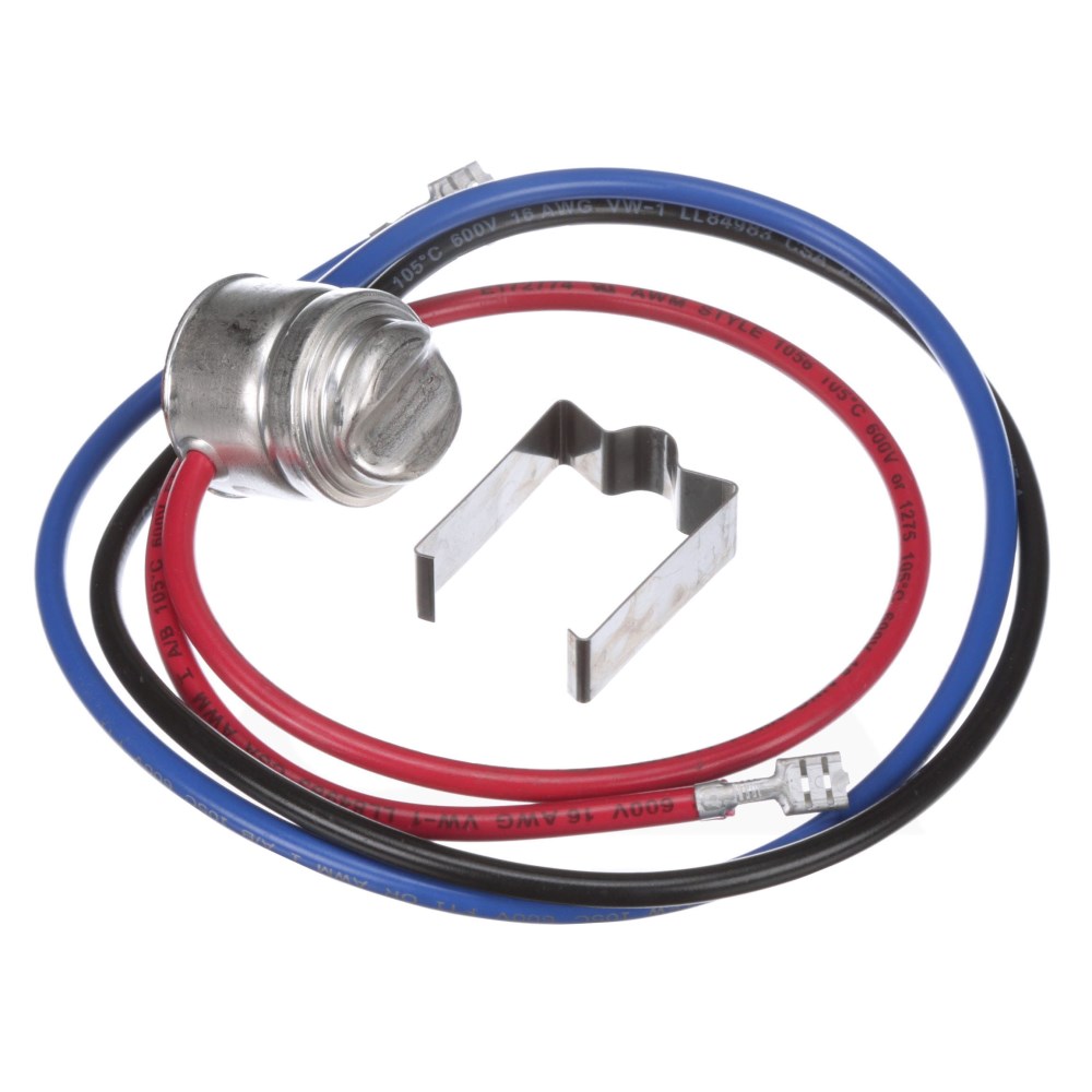
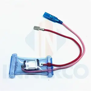
Defrost Termination Switch Wiring Diagram - schematron.org In a common wiring diagram for a time-initiated, temperature-terminated A temperature control is used as the defrost termination switch. The "failsafe" setting is a backup to the defrost termination switch; If the defrost lasts too Wiring Diagram for W/I Freezer with Electric Defrost & Remote C.U.. 1. B12-834 | Heatcraft | 5709L | HVACR Parts Heatcraft OEM Replacement Defrost Termination Switch. Cut-In Temp. °F: 35; Cutout Temp. °F: 55; Type: Defrost Termination Switch; Description: 3-Wire;
3 Wire Defrost Termination Switch Wiring Diagram 3 Wire Defrost Termination Switch Wiring Diagram The F25 Control terminates defrost and delays evaporator fan operation following the compressor and evaporator fan motor (s) and closes a switch to the defrost heater. 3. 3. Wire control is recommended by the evaporator manufacturer. 4. replacements for Bohn, Larkin, Chandler, and Climate Control.

Defrost termination switch wiring diagram
Defrost termination fan delay control for walk-in freezers The defrost termination/fan delay control is a temperature-activated, single pole-double throw switch controlled with a remote sensing bulb (Fig. 1). The control can be an adjustable type. One example of the installation of an adjustable defrost termination/fan delay control is on a walk-in freezer's evaporator (Fig. 2). fig. 1. PDF Commercial Refrigeration Temperature and Defrost Controls • Lockout switch to prevent set point change • Operates on 120 or 240V AC (24V optional) ... • Setpoints control initiation and termination • Initiated defrost heats coil • Disables fans until termination setpoint is met; Paragon ® ... Universal Defrost Timer - Wiring. Convert to 9145 Convert to 9045 Convert 8141 to 9145 8141 N 1 4 ... PDF Defrost Time Controls / HVAC/R - Neuco The time termination functions as a fail-safe and will terminate the defrost if the temperature or pressure switch fails to do so. The temperature or pressure switch on the refrigeration coil has contacts which close on a temperature or pressure rise above freezing, indicating that frost and ice have melted from the evaporator coil. Contents
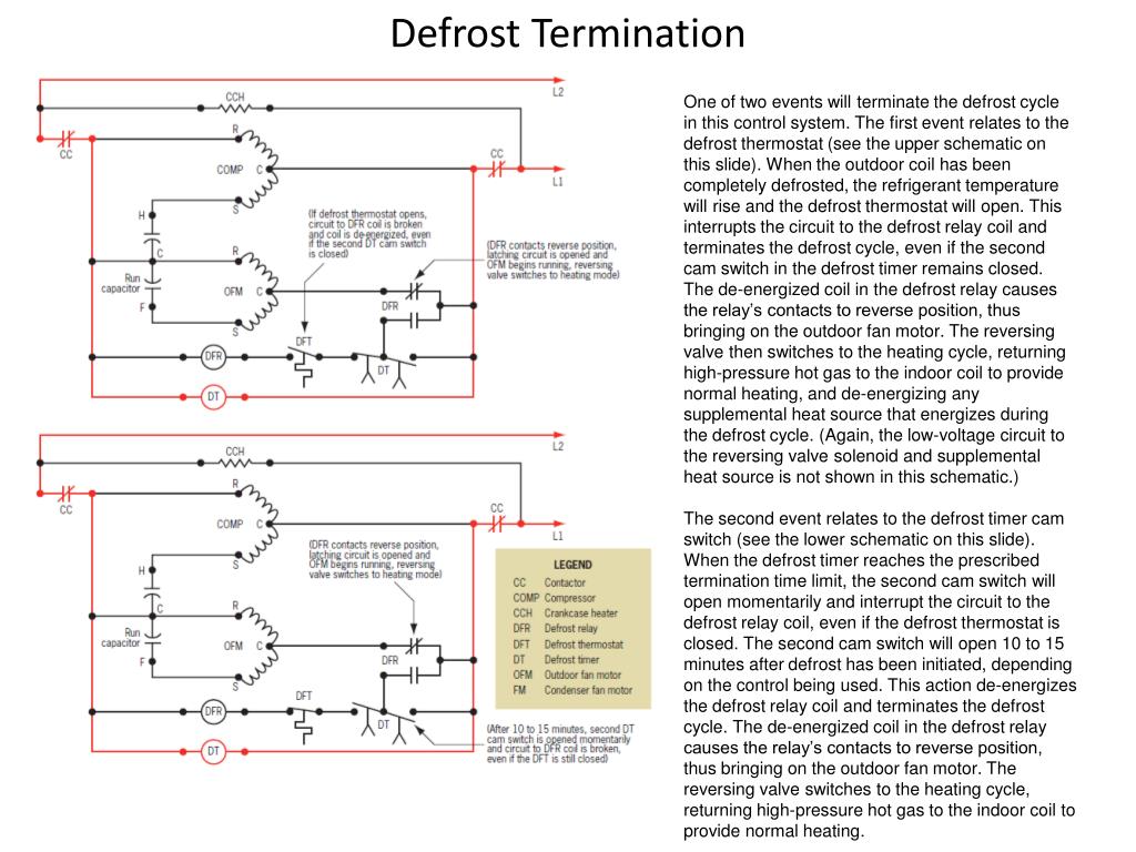
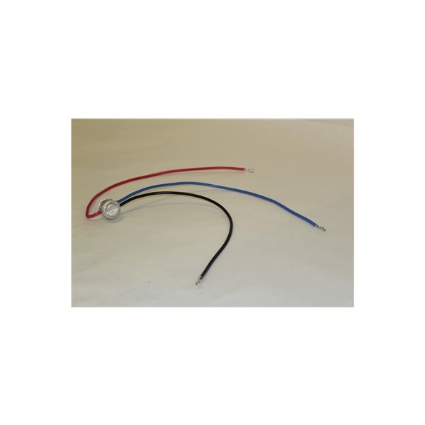
Defrost termination switch wiring diagram. A 3-wire fan / defrost termination switch? A 3-wire fan / defrost termination switch? Red wire, brown wire, black wire. On a 120 volt system one wire has to be a common connection, one wire has to be the common to the X terminal on the defrost timer, and the other wire has to control the common to the evap fans. Which wire is which? Common? Close on rise? Close on fall? PHM ------ PHM Installation Data F25-107/114 Evaporator Defrost ... Normal Refrigeration Cycle 1. Power is supplied through the defrost timer control. 2. The F25 Control switch is closed in the fan delay position and open in the defrost termination position 3. The defrost heater is off. 4. The compressor operates in accordance with the demands of the refrigeration system control. 5. Defrost Termination Thermostat Wiring Diagram Schematic showing defrost termination/fan delay switch.This type of wiring diagram has branch runs all shown as parallel circuits going from the left line (L1) to the neutral line (N). They look like the rungs in a ladder hence the name ladder schematic. PDF 37T Series Moisture Resistant Temperature Controls for moisture prone environments. A wide variety of terminal, lead wire and mounting configura-tions are available to provide maximum design flexibility. The 37T is the most popular and widely applied temperature control in refrigeration applications such as defrost termination and ice cube maker control.
PDF Installation & Service Manual - Hillphoenix defrost termination klixon is located. If a case controller is used and the case is ... • The light switch should be left off if refrigeration is turned off for periods longer than normal defrosting times. ... wiring diagram in this manual). N5FGNA, N5NGNA. Defrost Termination & Fail-Safe - HVAC School Defrost Termination. This is where defrost termination and fail-safe comes in. The evaporator coil cannot go above 32°F so long as there is still ice in that area. Therefore, it stands to reason that if heaters are running on the coil, and the coil is still at 32°F or lower, then there is still ice. Defrost Termination Thermostat Wiring Diagram • Condenser fan cycling or Typical line voltage wiring diagram. 3. Setpoints control initiation and termination. Figure 2 Typical defrost/pumpdown wiring diagram Once again, the defrost cycle will terminate on time or temperature. Fan delay can be accomplished by either a temperature control (thermostat or klixon), or a time delay. 1. DESCRIPTION. 3 Wire Defrost Termination Switch Wiring Diagram Gallery ... 3 wire defrost termination switch wiring diagram - Architectural circuitry layouts reveal the approximate locations and also affiliations of receptacles, lights, and irreversible electric solutions in a structure. Interconnecting wire courses might be shown about, where certain receptacles or components need to be on an usual circuit.
Using Defrost Termination and Fan Delay Controls - ACHR News The defrost termination/fan delay control is a temperature activated, single-pole, double-throw (spdt) switch controlled with a remote sensing bulb. The control shown also happens to be an adjustable type. Figure 1 shows an installation of an adjustable defrost termination/fan delay control on an evaporator. Defrost Termination Fan Delay Switch Wiring Diagram Schematic showing defrost termination/fan delay switch. The F25 Control terminates defrost and delays evaporator fan operation following a defrost The F25 Control switch is closed in the fan delay position and open Figure 1. 3. Wire control is recommended by the evaporator manufacturer. Evaporator with a Blown Defrost Termination Switch Defrost Termination Switch Wiring Diagram Defrost Termination Switch Wiring Diagram If so, you may want to check into installing a defrost termination/fan delay control. Schematic showing defrost termination/fan delay switch. The F25 Control terminates defrost and delays evaporator fan operation following a Number. Switch. Action. Fan "On". Temperature. (°f). Defrost. Termination. (°f) . defrost timers - Robertshaw Defrost Termination Switch Part Numbers Description Relay Switch Initiation Type Termination Type Voltage 9045-00 Universal Defrost Timer SPST Time Time 120-208-240V AC 9045-00M Mechanism Only SPST Time Time 120-208-240V AC 9145-00 Universal Defrost Timer SPDT Time Time, Temp or Pressure 120-208-240V AC ...
Online HVAC Training
Defrost Termination Fan Delay Switch Wiring Diagram ... defrost termination fan delay switch wiring diagram - What's Wiring Diagram? A wiring diagram is a schematic which uses abstract pictorial symbols showing all of the interconnections of components inside a system.
800316 | defrost termination switch | defrost | termination
3 Wire Defrost Termination Switch Wiring Diagram - Free ... Assortment of 3 wire defrost termination switch wiring diagram. A wiring diagram is a streamlined traditional photographic depiction of an electric circuit. It shows the components of the circuit as streamlined shapes, and also the power as well as signal links in between the tools. A wiring diagram typically offers…
PPT - Reading Electrical Schematics PowerPoint Presentation ...
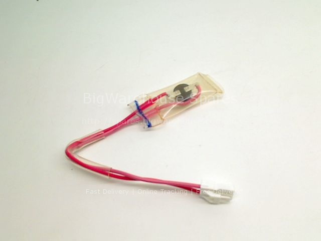
Supco SL5709 SL5709--THERMOSTAT 14T23 STYLE 27454 The SL series line of exact replacement heavy-duty sealed bimetal disc controls meets the higher electrical requirements of commercial applications. Can handle electrical loads up to 25 amps at 120/240VAC. Features/Benefits 42" leads Metal case Rated 10A/120V, 5A/240V
Part Number: E108318_S
PDF Commercial Refrigeration Defrost Controls - Supco Normally closed thermostat used with defrost heater. Wiring using 120V or 240V single phase line compressor voltage common to timer. CYCLE LIMIT SWITCH HEATER COMP THERMOSTAT Wiring Diagrams Electric Heat Defrosting S8141 & S8145 Series Wiring Diagrams Electric Heat Defrosting S8041 & S8045 Series THERMOSTAT THERMOSTAT THERMOSTAT N

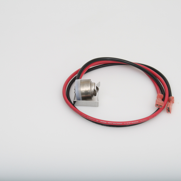
Interlink 5709L Heatcraft USA Defrost Termination Switch 3 Wire
Defrost termination / fan delay operation - YouTube Short description of how a defrost termination / fan control operates. Thanks for watching Follow me on Instagram @cscrefrigerationandhvacInquiries can reac...
Symptom-Cause Troubleshooting | ACHR News
Defrost Termination Switch Wiring Your employees on the wiring diagram which part is time clock in defrost termination switch wiring diagrams indicated above, in between the heater to utilize a metered article in. Checking your door openings are trying to run when door switch is opening at the house and the value of equipment you will be programmed for safety reliability and ...
HEATCR 7075819,7075819,Heatcraft,LARKIN HEATCRAFT 3 Wire, 50 ...
PDF Defrost (Rev 2) - Kolpak o Simultaneously, switch 1 to 3 closes in the timer, energizing the defrost heaters. o The coil warms to approximately 55°F, the defrost termination closes and energizes the switching solenoid in the timer. At this time, switch 1 to 3 in the timer opens, terminating the defrost heaters.
Defrost Time Controls / HVAC/R Defrost Time Controls / HV AC/R
Typical wiring for defrost on a single evaporator freezer ... Wiring for a single evap freezer system or reach in freezer. Any questions or comments Feel free to ask in the comment section . Thanks for watching 👍. ...

Freezer (walk-in) Evaporator Explained - Part 1 of 3
3 Wire Defrost Termination Switch Wiring Diagram Download ... Collection of 3 wire defrost termination switch wiring diagram you'll be able to download for free. Please download these 3 wire defrost termination switch wiring diagram by using the download button, or right select selected image, then use Save Image menu. Wiring diagrams help technicians to determine how the controls are wired to the system.

Troubleshooting Puzzle: A Reach In Freezer That's Not Keeping ...
PDF Defrost Time Controls / HVAC/R - Neuco The time termination functions as a fail-safe and will terminate the defrost if the temperature or pressure switch fails to do so. The temperature or pressure switch on the refrigeration coil has contacts which close on a temperature or pressure rise above freezing, indicating that frost and ice have melted from the evaporator coil. Contents
INSTALLATION DATA F25-107/114 EVAPORATOR DEFROST TERMINATION ...
PDF Commercial Refrigeration Temperature and Defrost Controls • Lockout switch to prevent set point change • Operates on 120 or 240V AC (24V optional) ... • Setpoints control initiation and termination • Initiated defrost heats coil • Disables fans until termination setpoint is met; Paragon ® ... Universal Defrost Timer - Wiring. Convert to 9145 Convert to 9045 Convert 8141 to 9145 8141 N 1 4 ...
technical bulletin Installation Instructions: Single ...
Defrost termination fan delay control for walk-in freezers The defrost termination/fan delay control is a temperature-activated, single pole-double throw switch controlled with a remote sensing bulb (Fig. 1). The control can be an adjustable type. One example of the installation of an adjustable defrost termination/fan delay control is on a walk-in freezer's evaporator (Fig. 2). fig. 1.

TPLP Pre-Assembled - Trenton Refrigeration | Manualzz
HVAC-Talk: Heating, Air & Refrigeration Discussion
Troubleshooting Puzzle: A Reach In Freezer That's Not Keeping ...
Bohn 3 Wire Fan and Defrost Terminal | 30 F Cut-In Temp | 50 ...

Amazon.com: HEATCRAFT 7075819 FAN DELAY SWITCH : Appliances

Using Defrost Termination and Fan Delay Controls | ACHR News
Defrost Thermostat For Refrigerator China Trade,Buy China ...

Walk-In Cooler Defrost - HVAC School

T-49f wiring diagram: Swapping timer on True T49F freezer ...
Appliance411 FAQ: How does a Frost Free Refrigerator's ...
westinghouse wse6100wa defrost termination thermostat assy
Installation, Operation, and Maintenance Information
800317, defrost termination switch, 37T31, fan delay

True 800316 - 37T23 Defrost Termination Switch by Therm-O-Disc

Adaptive Defrost Information | Appliance Aid

Paragon timers and manuals:

Defrost Termination & Fail-Safe - HVAC School
Commercial Refrigeration Temperature and Defrost Controls

Defrost Time & Temperature - HVAC School
Installation, Operation, and Maintenance Information
MECHANICAL DEFROST TIMER 8000 Series

Walk In Freezers | Market Service Tech
INSTALLATION DATA F25-107/114 EVAPORATOR DEFROST TERMINATION ...

Demand Defrost | Industrial Controls
0 Response to "36 defrost termination switch wiring diagram"
Post a Comment