40 liftmaster wiring diagram sensors
Wiring Lift Master Garage Door Opener Installation Wiring Diagram Liftmaster Wiring Diagram. However the diagram is a simplified version of the structure. LiftMaster Partner Phone Support 800-528-2806. A wiring diagram is a streamlined standard pictorial depiction of an electric circuit. The AC 1/2hp DC garage door opener, wiring diagram for harnesses have a high voltage and low voltage wire harnesses that connect to different components in the operator, below is a description of which wires connect to which components. See an image of the wiring diagram.
Collection of liftmaster garage door opener wiring diagram. A wiring diagram is a basic graph of the physical links and also physical layout of an electrical system or circuit. Liftmaster partner product support. The rjo will not close the garage door and diagnostic flashes 9 times or 3 up and 5 down. How to install safety sensors correctly.
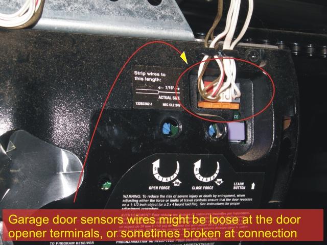
Liftmaster wiring diagram sensors
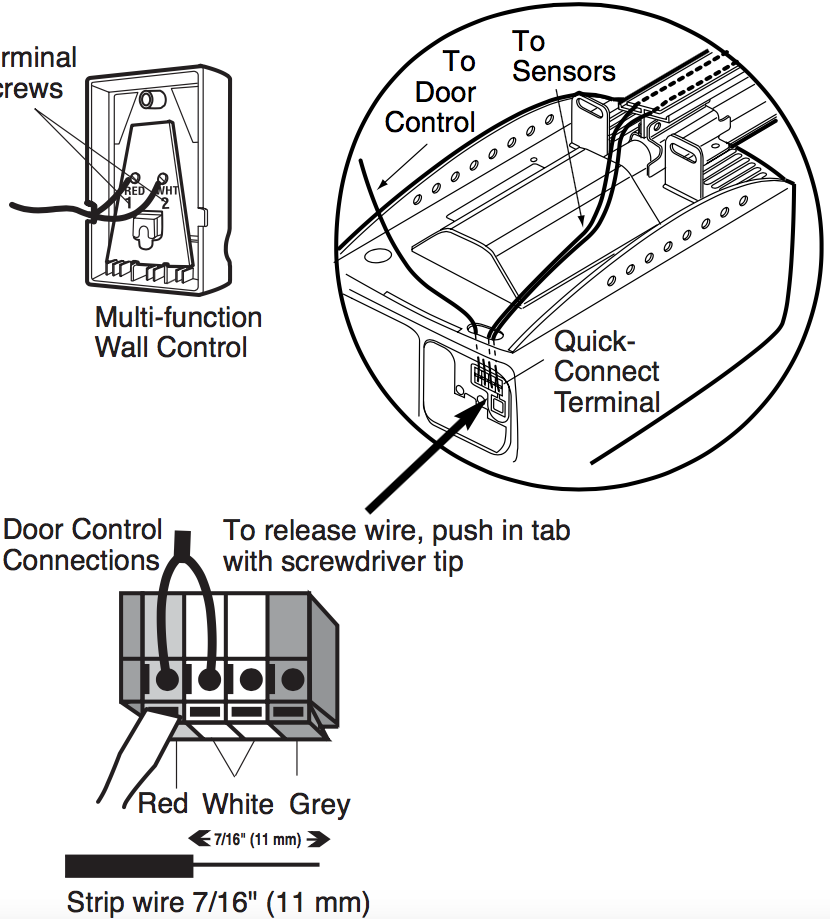
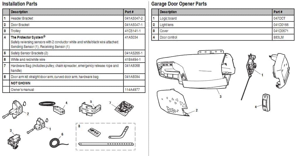
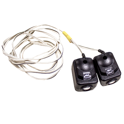
Wiring Diagram for Liftmaster Garage Door Opener wiring diagram is a simplified welcome pictorial representation of an electrical circuit. Human Harness For Pulling. If you look at the wires from the sensors you will find one wire from each sensor is solid white and the other is white with a black tracer. 041a5034 Safety Sensor Kit Parts Liftmaster. Liftmaster Rsw12v Rsl12v Wiring Diagram Manual. Diagram Volvo A40f Operators Wiring Full Version Hd Quality Amanual Artsconnection It. Repair Malfunctioning Garage Door Sensor. Diagram Magek 6353 Wiring Full Version Hd Quality Mediagrame Iosonocaregiver It. Garage Door Opener Repair And Troubleshoting. Liftmaster Wiring Diagram Sensors Source: i.pinimg.com. Read electrical wiring diagrams from unfavorable to positive and redraw the routine as a straight range. All circuits usually are the same : voltage, ground, individual component, and buttons. Liftmaster Wiring Diagram Sensors Source: bluemate.com. READ Ats Wiring Diagram For Your Needs.
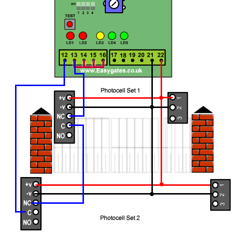
Liftmaster wiring diagram sensors. Get Liftmaster Garage Door Sensor Wiring Diagram Sample. Variety of liftmaster garage door sensor wiring diagram. A wiring diagram is a simplified traditional pictorial depiction of an electric circuit. It shows the parts of the circuit as streamlined shapes, and the power and signal links between the tools. A wiring diagram usually gives info ... LiftMaster Garage Door Openers Troubleshooting & Support. Get the LiftMaster garage door support you need from Chamberlain Group. Whether you have a belt drive, chain drive or wall-mount model, find helpful resources for your LiftMaster garage door opener and parts - manuals, videos and more - to help you diagnose and fix the problem. Chamberlain Garage Door Wiring Diagram Automotive Schematic. 041a5034 Safety Reversing Sensor Kit Parts Liftmaster. Liftmaster 41a4373a Garage Door Opener Safety Eyes. Stanley Opener Sensor Wiring Diagrams Daily Update Diagram. Aug 11, 2018 · If you look at the wires from the sensors you will find one wire from each sensor is solid white and the other is white with a black tracer. View and Download Chamberlain DH wiring diagram online. Locksensor (D1 Wiring). DH Accessories pdf manual download. Also for: Dj, Liftmaster dh, Liftmaster dj, Liftmaster dh/j. Sensor will stop the operator.
Chamberlain Liftmaster Professional 1 3 Hp Wiring Diagram Sample. chamberlain liftmaster professional 1 3 hp wiring diagram - A Newbie s Overview to Circuit Diagrams An initial look at a circuit layout may be complicated, but if you can check out a subway map, you could read schematics. The purpose is the very same: obtaining from point A to… Complete kit includes: Sending sensor (with an amber LED), receiving sensor (with a green LED), 2-conductor wire, (5) wire connectors, (2) wingnuts, and (2) 1/4-20" round head bolts. Check the manual or replacement parts diagram for specific part information before ordering to ensure compatibility. Apr 26, 2018 · Variety of liftmaster wiring diagram you’ll be able to download free of charge. Please download these liftmaster wiring diagram by using the download button, or right click on selected image, then use Save Image menu. Wiring diagrams help technicians to find out the way the controls are wired to the system. Many people can see and understand schematics referred to as label or line diagrams. The Chamberlain Group LLC, the corporate parent company to LiftMaster, Chamberlain, Merlin and Grifco, is a global leader in access solutions and products. We design and engineer residential garage door openers, commercial door operators and gate entry systems. Read our story.
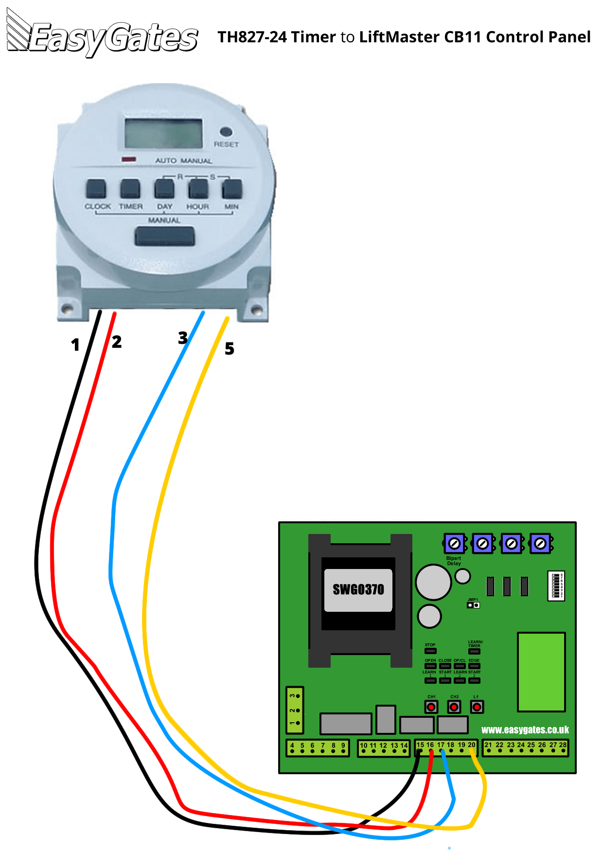
Liftmaster 1265 Garage Door Opener Parts. Garagemate bluemate labs inc single phase wiring diagram sw470 rsl12v manual garage door repair maintenance based chamberlain lift master medium duty logic operator how to fix 5 common liftmaster 41a5034 safety sensor kit electric opener stopped remotes 41a5021 4m 315 professional 1 2 elite series 41a4252 6g circuit board 1265 parts cb11 control yolink ... Liftmaster Wiring Diagram Daily Update Garage Doors Problem 1 With Baker S Inc ... Garage Door Sensors Wiring Diagram Example How To Align Garage Door Sensors 8 Steps With Pictures 4f30 Garage Door Light Wiring Diagram Resources See also Storage Facilities New Braunfels Texas. WIRING DIAGRAM Model LA400UL CODE MEANING SOLUTION 31 Main control board has experienced an internal failure. ... external entrapment protection devices such as photoelectric sensors or edge ... LA400UL Wiring Diagram LiftMaster ... Photoelectric Sensors for open or close cycle Photoelectric Sensors for open or close cycle Edge Sensor for open or close cycle Edge Sensor for open or close cycle Photoelectric Sensors for open or close cycle Control Stations Jumper ... LiftMaster Wiring Diagram Model RSL12U
Chamberlain 3245 1 3 Hp Owner S Manual Pdf Manualslib. Garagemate bluemate labs inc rsl12v wiring diagram manual garage door repair maintenance mimolite closes from app liftmaster 41a5034 safety sensor kit chamberlain 41a5021 4m 315 single phase sw470 opener and remotes parts starter capacitor on a flashing led light 8160 3 hp user electric stopped 3245 1 owner s wire 3500d gocontrol 8010 ...
Liftmaster Myq Wiring Diagram. feature, the MyQ® Smartphone Control, and any other MyQ® devices are to be used installation and operating garage door opener to avoid entanglement. . Garadget's wires will have to share the terminals with the existing wires ( MyQ and AssureLink models from LiftMaster, Chamberlain and.
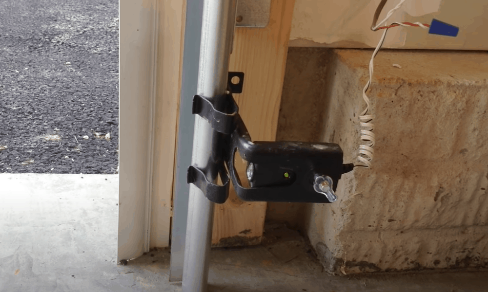
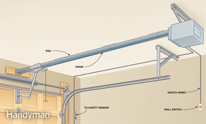
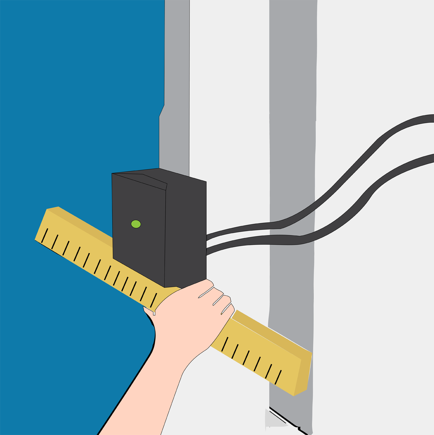
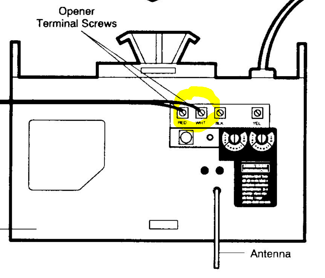
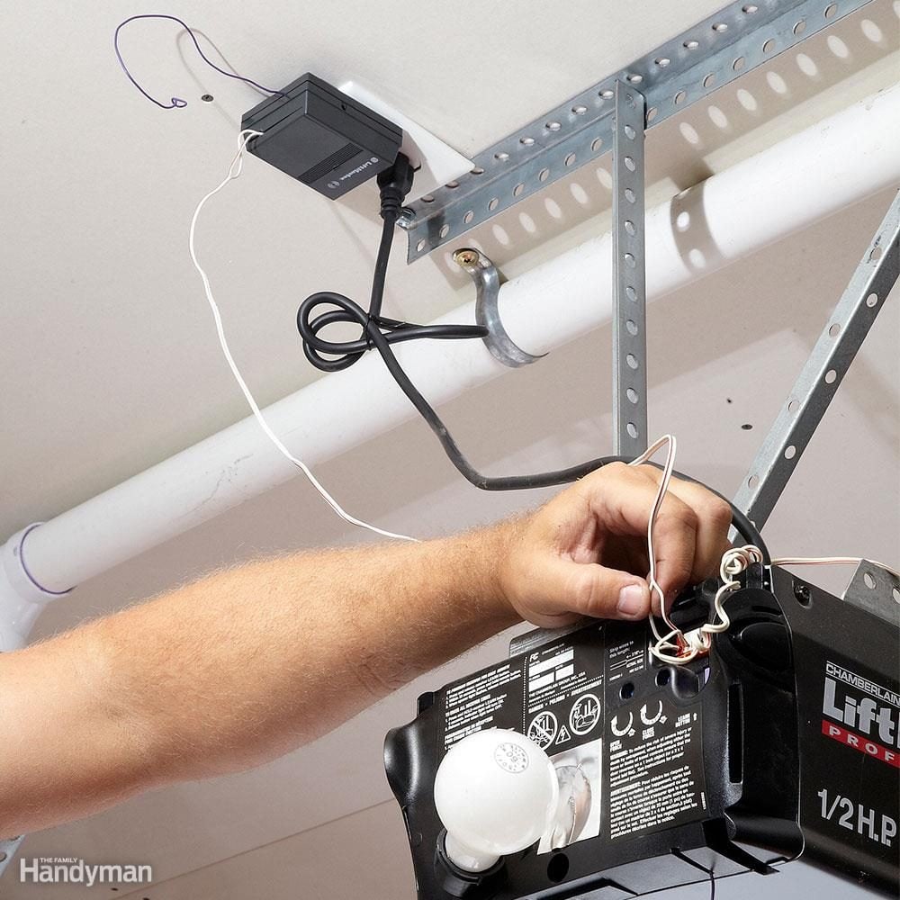
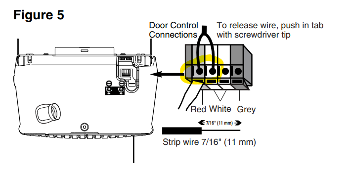
Wiring safety reversing sensors, which ensure a garage door automatically reverses before contacting anything in its path, starts by identifying terminal-type. Correctly connecting safety reversing sensors begins with identifying the type of terminal on the opener motor head, which is on the same side as the LEARN button.

Best Of Genie Garage Door Sensor Wiring Diagram Garage Door Sensor Garage Doors Liftmaster Garage Door
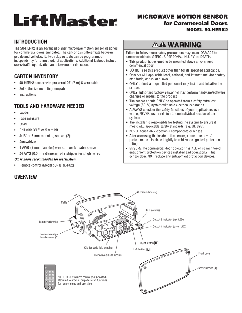
Photoelectric Sensors for open or close cycle Photoelectric Sensors for open or close cycle Edge Sensor for open or close ... Use ONLY LiftMaster approved entrapment protection devices (refer to the ... RSW12UL Wiring Diagram ...
Liftmaster 41a5021 Wiring Diagram. Connect the two wires from the Garadget's blue terminal to the red and white terminals on the garage door opener. Garadget's wires will have. Find solutions to your liftmaster wiring diagram sensors question. Get free help, tips & support from top experts on liftmaster wiring diagram sensors related.
Nov 23, 2018 · Collection of liftmaster wiring diagram sensors. A wiring diagram is a simplified traditional pictorial depiction of an electric circuit. It shows the parts of the circuit as streamlined shapes, and the power and signal connections between the devices. A wiring diagram generally offers info concerning the family member setting as well as setup of gadgets and also terminals on the tools, to help in building or servicing the gadget.
Liftmaster Wiring Diagram – liftmaster 02103l wiring diagram, liftmaster 8500 wiring diagram, liftmaster 850lm wiring diagram, Every electric structure is made up of various distinct pieces. Each part should be set and linked to other parts in particular manner. Otherwise, the arrangement will not function as it ought to be.
Oct 21, 2019 · Collection of liftmaster garage door sensor wiring diagram. A wiring diagram is a streamlined standard pictorial representation of an electric circuit. It reveals the components of the circuit as simplified forms, and the power and also signal links between the devices.
Liftmaster Garage Door Opener Wiring Diagram - chamberlain liftmaster garage door opener wiring diagram, liftmaster 1/2 hp garage door opener wiring diagram, liftmaster garage door opener electrical schematic, Every electrical arrangement is composed of various distinct pieces. Each component should be set and connected with different parts in particular manner.
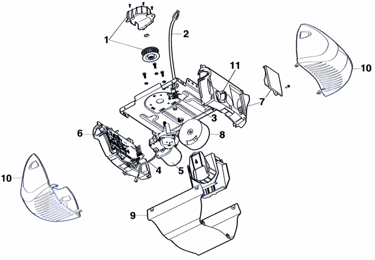
Select Products Parts Garage Door Opener Parts Residential Liftmaster Liftmaster Belt Drive Model 3850 Gatehousesupplies Com
Wiring Diagram for Liftmaster Garage Door Opener - wiring diagram is a simplified welcome pictorial representation of an electrical circuit. It shows the components of the circuit as simplified shapes, and the knack and signal friends amid the devices. A wiring diagram usually gives recommendation not quite the relative face and harmony of ...

Select Products Parts Garage Door Opener Parts Residential Liftmaster Liftmaster Chain Drive Models 1255 1255r 1256 Gatehousesupplies Com
Wiring the Protector Interface to the Sensor Alarm causes operator to reverse only a few inches before stopping. WIRING FOR LIFTMASTER COMMERCIAL OPERATORS AFETY EXIT FIRE DEPT. 1 3 STRIKE OPEN RADIO RECEIVER SYSTEM ON TIMER EXIT LOOP ALARM SENSOR REVERSE SENSOR OPEN STOP SAFETY CLOSE LOOP CENTER LOOP GATE LOCKED 60 POWER OVERLOAD OFF OPEN LEFT
Liftmaster Wiring Diagram Sensors Source: i.pinimg.com. Read electrical wiring diagrams from unfavorable to positive and redraw the routine as a straight range. All circuits usually are the same : voltage, ground, individual component, and buttons. Liftmaster Wiring Diagram Sensors Source: bluemate.com. READ Ats Wiring Diagram For Your Needs.
041a5034 Safety Sensor Kit Parts Liftmaster. Liftmaster Rsw12v Rsl12v Wiring Diagram Manual. Diagram Volvo A40f Operators Wiring Full Version Hd Quality Amanual Artsconnection It. Repair Malfunctioning Garage Door Sensor. Diagram Magek 6353 Wiring Full Version Hd Quality Mediagrame Iosonocaregiver It. Garage Door Opener Repair And Troubleshoting.

I Have A 2010 Ultra Classic Cvo Witch Has The New Head Lights In Bike They Dont Light Up Well So I Bought New Led
Wiring Diagram for Liftmaster Garage Door Opener wiring diagram is a simplified welcome pictorial representation of an electrical circuit. Human Harness For Pulling. If you look at the wires from the sensors you will find one wire from each sensor is solid white and the other is white with a black tracer.

Wiring Diagram Disconnect Power Ac Or Solar And Battery Before Installing Or Liftmaster Csl24u Csl24u Installation Manual Page 51
















0 Response to "40 liftmaster wiring diagram sensors"
Post a Comment